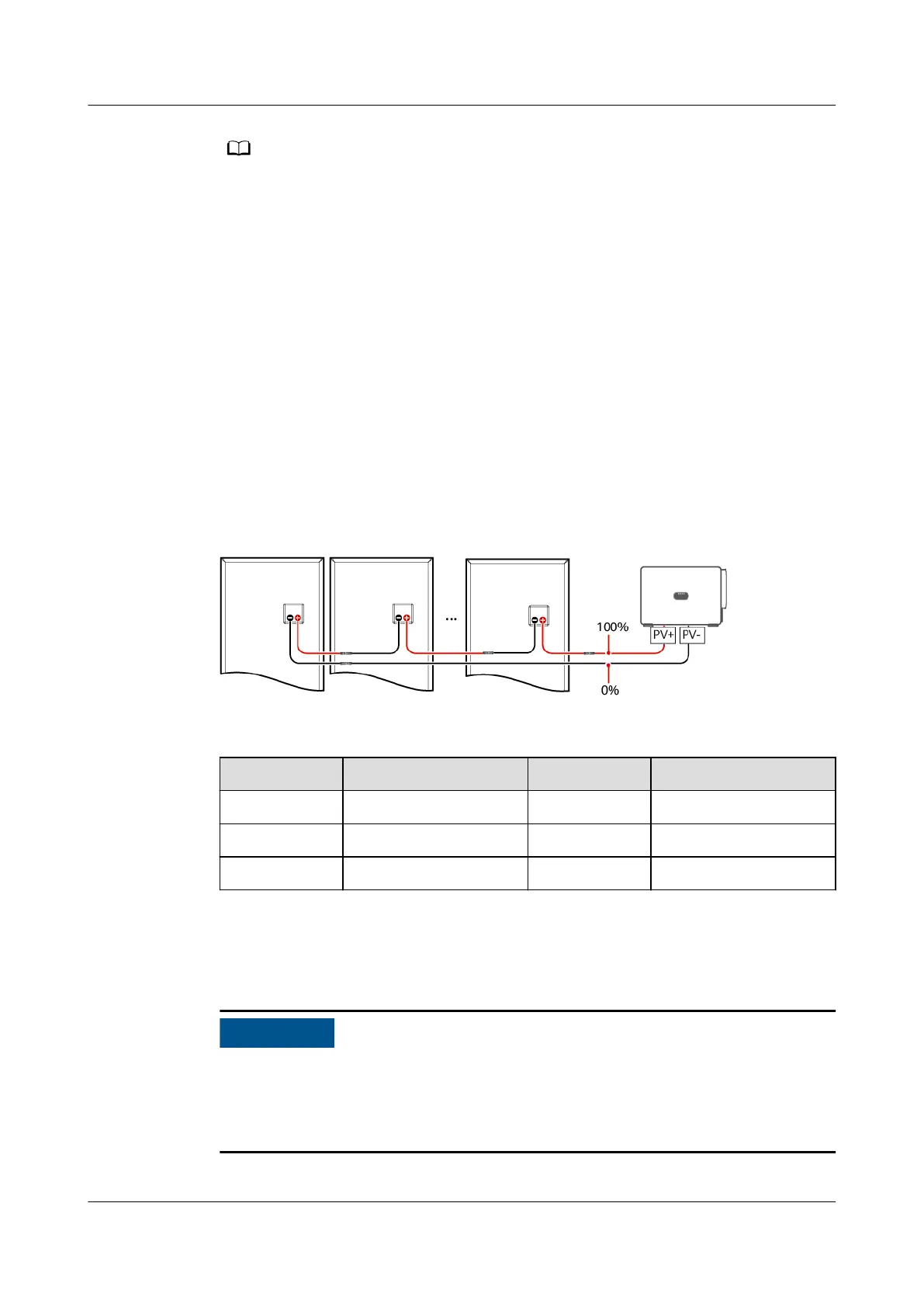
● The positive and negative terminals of a PV string are connected to the PV+ and PV–
terminals of the SUN2000, respectively. The 0% position corresponds to the PV–
terminal, and the 100% position corresponds to the PV+ terminal. Other percentages
indicate that the fault occurs on a PV module or cable in the PV string.
● Possible fault position = Total number of PV modules in a PV string x Percentage of
possible short-circuit positions. For example, if a PV string consists of 14 PV modules
and the percentage of the possible short-circuit position is 34%, the possible fault
position is 4.76 (14 x 34%), indicating that the fault is located near PV module 4,
including the adjacent PV modules and their cables. The SUN2000 has a detection
precision of ±1 PV module.
● For details about the PV strings corresponding to the MPPT that may be faulty, see
Table 8-2. The fault can be located only to the MPPT level. Perform the following steps
to connect the PV strings corresponding to the faulty MPPT to the SUN2000 one by one
to further locate and rectify the fault.
● When a non-short-circuit fault occurs, the possible short-circuit percentage is not
displayed. If the insulation resistance is greater than 0.001 MΩ, the fault is not related
to short circuit. Check all PV modules in the faulty PV string one by one to locate and
rectify the fault.
Figure 8-9 Denition of the percentage of the short-circuit position
Table 8-2 Mapping between MPPTs and PV strings
MPPTn
PV String MPPTn PV String
MPPT1 PV1–PV4 MPPT2 PV5–PV9
MPPT3 PV10–PV14 MPPT4 PV15–PV18
MPPT5 PV19–PV23 MPPT6 PV24–PV28
Procedure
If the irradiance or the PV string voltage is too high, the insulation resistance fault
location may fail. In this case, the fault location status on the Alarm details
screen is Conditions not met. Perform the following steps to connect PV strings to
the SUN2000 one by one to locate the fault.
SUN2000-(250KTL, 280KTL, 300KTL, 330KTL) Series
User Manual 8 System Maintenance
Issue 07 (2023-06-30) Copyright © Huawei Technologies Co., Ltd. 83
 Loading...