2624 2624HS 2628 2630 Series Tooling Alcoa Fastening Systems
5
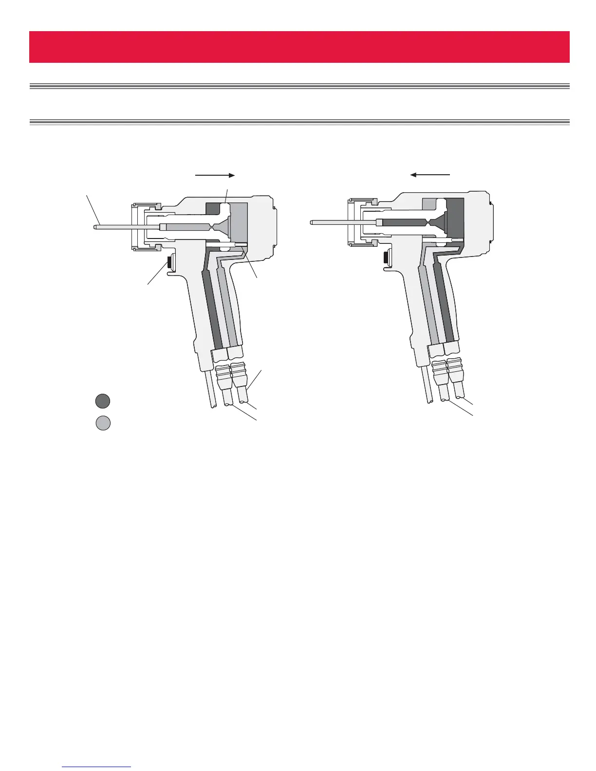
When the trigger is depressed, a solenoid
operated valve in the POWERIG® directs
pressurized hydraulic fluid through the
PULL hose to the front side of the piston,
and allows fluid on the RETURN side to
flow back to the tank (Fig 1a). The piston
and nose assembly collet moves rearward
installing the fastener. When the piston
reaches the end of the PULL stroke, it
uncovers flats on the rear end of the
unloading valve. These flats are designed
to provide a passage for hydraulic fluid
from the PULL side to the RETURN side of
the piston, “unloading” or “dumping” the
pressurized fluid back to the tank (Fig 1a).
When the trigger is released the solenoid is
de-energized and the valve directs pressur-
ized fluid to the rear side of the piston and
allows fluid on the PULL side to flow back
to the tank (Fig. 1b). This causes piston
and collet to move forward and pushes the
nose assembly and tool off the swaged
(installed) fastener. When the piston reach-
es the end of the return stroke, pressure is
built up, causing the power rig to shut off,
completing the cycle.
P
P
RINCIPLE
RINCIPLE
OF
OF
O
O
PERATION
PERATION
Pull Pressure (Pull Cycle)
Fig. 1(a)
Return Pressure (Return Cycle)
Fig. 1(b)