TRANSMISSION—OVERDRIVE
31
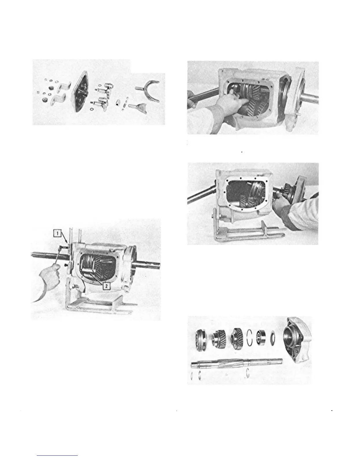
involves removal of the shift levers and forks and tapping
out the shift shafts from the cover. Care should be taken to
prevent, loss of interlock sleeve, balls, spring or pin (Fig.
21).
FIGURE 21—Transmission Cover and
Shift Lock Assembly
Removing Clutch Shaft Bearing
After removing the bearing cap and gasket, remove the
clutch shaft snap ring, spacer washer, and the bearing lock
ring.
The front bearing can be removed from the clutch shaft
by using bearing puller (J-6654) together with a thrust
yoke (J-6652) to prevent damage to the synchronizer
clutch (Fig. 22).
1. Bearing Puller (J-6654) 2. Thrust Yoke (J-6652)
FIGURE 22—Use Bearing Puller and Thrust
Yoke to Pull the Front Bearing to Prevent
Damage to the Synchro Clutch
Removing Transmission Main Shaft
With the front bearing removed from the clutch shaft, pull
the shaft as far forward as possible.
NOTE: The clutch shaft cannot be removed
from the front of the transmission case.
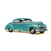
Grasp the main shaft and its components and separate
the main shaft from the clutch shaft (Fig. 23). When
separated, slide the main shaft and its components out the
rear of the transmission case (Fig. 24).
FIGURE 24—Removing Main Shaft Assembly
from the Transmission Case
Disassembly of Transmission Main Shaft
Set the main shaft assembly on a bench and remove the
synchro-clutch spacer washer and lock ring. The synchro-
clutch, second speed, and first and reverse sliding gears
may then be removed from the transmission main shaft
(Fig. 25 ).
FIGURE 25—Transmission Main Shaft
Assembly
FIGURE 23—Separate Clutch Shaft and Main
Shaft Assembly