EasyManua.ls Logo

Hughes & Kettner TubeMeister 18 Series User Manual

Hughes & Kettner TubeMeister 18 Series
32 pages
To Next Page IconTo Next Page
Page #1 background imageLoading...
Page #1 background image
Service Documents
Confidential, for authorized service technicians only!
Do not disclose this information to or share these documents
with third parties.
Vertraulich! Nur für autorisierte Servicetechniker!
Nicht zur Weitergabe an Dritte freigegeben!
TECHNICAL SERVICE:
Stamer Musikanlagen GmbH Magdeburger Str. 8 66606 St.Wendel Germany
Music & Sales P.E. GmbH Leipziger Str. 3 66606 St.Wendel Germany
Note!
The components used in this product - particularly parts
affecting safety as well as speakers and transformers -
were developed and manufactured to certain specifications.
Please use original spare parts only to ensure the product
remains fully functional and safe.
Achtung!
Die in diesem Produkt verwendeten Komponenten, insbeson-
dere sicherheitsrelevante Teile, Lautsprecher und Transforma-
toren wurden nach spezifischen Vorgaben entwickelt und ge-
fertigt. Bitte benutzen Sie ausschließlich Original-Ersatzteile
nur so ist die volle Funktionalität und Sicherheit gewährleistet.
HU0910
TM 18
Head
Question and Answer IconNeed help?

Do you have a question about the Hughes & Kettner TubeMeister 18 Series and is the answer not in the manual?

Hughes & Kettner TubeMeister 18 Series Specifications

General IconGeneral
Power Output18 Watts
Preamp Tubes3 x 12AX7
Power Tubes2 x EL84
ReverbDigital Reverb
Weight5 kg
Channels2 Channels
Effects LoopYes
Direct OutputYes (Red Box DI)
Power SoakYes (0W, 1W, 5W, 18W)
FootswitchOptional (Channel Switching, Reverb On/Off)
Inputs1 x 1/4" Instrument Input
Special FeaturesPower Soak, Red Box DI
Outputs1 x XLR

Summary

Connections and Control Features

Front Panel Controls and Operation

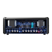
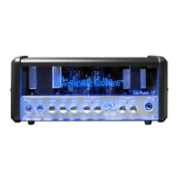
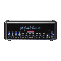
Explains the function of each front panel control and channel for operation.

Rear Panel Connections and Features

Details rear panel I/O, effects loop, reverb, footswitch, Red Box, and Power Soak.

Standard Setup and Cable Connections

Mains Power and Speaker Connections

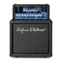
Instructions for connecting mains power and speaker cabinets, including safety advice.

Tube Safety Control (TSC)

TSC Status Monitoring and Manual Checks

Explains LED indicators for tube status and manual bias checks for optimal performance.

Technical Specifications

Amplifier and Cabinet Specifications

Lists detailed electrical, physical, and performance data for the amplifier and cabinet.

Exploded View and Parts Lists

Mainboard Assembly Diagram and Parts

Diagram showing the mainboard layout and identification of its parts.

Mainboard Component Identification

Mainboard Component Layout Views

Visuals of the mainboard showing component placement on both top and bottom sides.

Mainboard Spare Parts

Mainboard Spare Parts List

Detailed list of spare parts for the mainboard with reference designators.

Rearboard Assembly and Parts

Rearboard Assembly Diagram and Parts

Diagram showing the rearboard layout and identification of its parts.

Rearboard Spare Parts

Rearboard Spare Parts List

Detailed list of spare parts for the rearboard with reference designators.

LED Board Assembly and Parts

LED Board Assembly Diagram and Parts

Diagram showing the LED board layout and identification of its parts.

LED Board Spare Parts

LED Board Spare Parts List

Detailed list of spare parts for the LED board with reference designators.

Wiring Diagram

Overall Wiring Schematic

Illustrates the electrical connections between major components and power.

Mainboard Schematic

Mainboard Circuit Diagram

Detailed schematic of the mainboard's electronic circuitry.

Rearboard Schematic

Rearboard Circuit Diagram

Detailed schematic of the rearboard's electronic circuitry.

LED Board Schematic

LED Board Circuit Diagram

Detailed schematic of the LED board's electronic circuitry.

Reverb Module Schematic

Reverb Module Circuit Diagram

Detailed schematic of the reverb module's electronic circuitry.

Tube Bias Regulator Schematic

Tube Bias Regulator Circuit Diagram

Detailed schematic of the tube bias regulator's electronic circuitry.

Main PCB Layout

Main PCB Top Side Component Placement

Visual layout of components on the top side of the main PCB.

Main PCB Layout

Main PCB Bottom Side Component Placement

Visual layout of components on the bottom side of the main PCB.

PCB Component Layouts

Rear and LED PCB Component Placement

Visual layout of components for the rear and LED PCBs.

Auto PCB Layout

Auto PCB Component Placement

Visual layout of components for the Auto PCB.

Related product manuals