Operation: chassis
93
Electro-hydraulic system (option)
1
2
3
4
5
6
7
8
Battery box
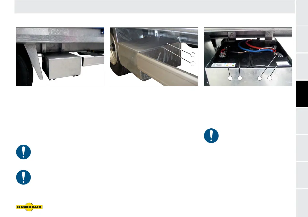
Fig. 40 Battery box on side under the chassis
The battery box as a galvanised sheet
metal box is located in the direction of
travel on the left.
The battery box is not watertight.
The power from the batteries
may only be used to supply the
electro-hydraulic unit with
power.
The batteries must be
maintained on a regular basis -
see section entitled
Maintenance starting on page
264.
Fig. 41 Battery box closed
1 Cover
2 Wing nut
Opening
Unscrew the wing nuts (Fig. 41/2) on
the right and left sides.
Carefully pull the cover (Fig. 41/1)
upwards.
Set down the cover and wing nuts
safely to avoid damage.
Closing
Fit the cover and firmly tighten down
the wing nuts.
Fig. 42 Battery box, open
1 Danger notices / warnings
2 Batteries (2x 44 Ah, 12 V)
3 Clamping point
4 Date of manufacture
Charging
The full power of the batteries is
sufficient for approx. 4 actuation
cycles.
Check the power of the batteries on a
regular basis (Fig. 42/2).
Note the date of manufacture
(Fig. 42/4) of the batteries.
Charge the batteries in the event of
reduced power (see section entitled
Maintenance, page 266).
F - 026 F - 086
1
2
F - 024
1
2
3
4


 To Next Page