Do you have a question about the Humminbird CHIRP and is the answer not in the manual?
Details on recommended certified installation by approved installers and operational instructions.
Warning against installing the product in hazardous or flammable atmospheres.
Warning about dangerous high voltages within the scanner unit and precautions.
Hazards associated with microwave radiation and effects on cardiac pacemakers.
Warning against connecting the unit to a system with positive grounding.
Guidance on authorized service personnel and user non-serviceable components.
Recommendations for maintaining adequate distance from magnetic compasses to prevent interference.
General warnings about navigational aid use and chart data.
Information for international customers regarding product versions and regional compliance.
Statement on compliance with IEEE C95.1 standard for human exposure to RF fields.
Statement on conformance with ICNIRP guidelines for exposure to electromagnetic fields.
Declaration of compliance with R&TTE directive 1999/5/EC.
Intended use for leisure marine boats and workboats, not covered by IMO/SOLAS regulations.
Advises checking licensing requirements for radar installation and operation.
Warning about unauthorized modifications violating FCC rules.
Statement on Humminbird's commitment to environmental regulations.
Information on the EU directive for waste electrical and electronic equipment disposal.
Statement on product design and potential exclusion from RoHS directive scope.
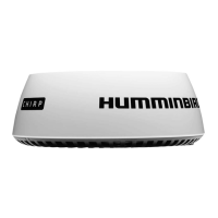
Outlines the installation steps covered in the manual for the Humminbird Radar scanner.
Instructions to unpack the box and confirm contents against the provided illustration.
Guidance on determining necessary cables for connecting the radar scanner based on Humminbird model.
Importance and components of creating a schematic diagram for installation planning.
Instructions on preparing the mounting surface by clearing and drilling mounting holes.
Key considerations for selecting an optimal mounting location for the radar scanner on a vessel.
Guidance on mounting the scanner unit on the vessel's centerline for unobstructed view.
Considerations for choosing a mounting height to optimize range and avoid pitching/rolling issues.
Advice on positioning the scanner to avoid interference from structures and other antennas.
Explanation of how structures can cause blind spots and false echoes, and how to identify them.
Recommendations for separating Humminbird equipment from other transmitting devices and radar beams.
Requirements for the mounting surface, including flatness, stability, and angle considerations.
Method of using wedges or washers to compensate for vessel bow rise at cruising speed.
Information on mounting the radar scanner directly or using a bracket, and keeping the drain tube clear.
Requirement for access to the underside for installing mounting bolts.
Illustration and explanation of installing a radar scanner guard for sailing vessels.
Important location requirements for installing multiple radar scanners on the same vessel.
Guidelines to prevent excessive cable bending and maintain a minimum bend radius.
Importance of providing adequate strain relief for connectors to prevent pull-out.
Methods for protecting cables from physical damage, heat, and environmental exposure.
Steps to prepare the mounting location, including cleaning, aligning templates, and drilling holes.
Procedure to test hardware by checking bolt protrusion through the mounting surface.
Instructions for connecting power and data cables to the radar scanner before mounting.
Illustrations showing different examples of routing power and data cables for installation.
Detailed steps for physically installing the radar scanner onto the prepared mounting surface.
Illustration and instructions for mounting the scanner unit, including bolt torque specifications.
Instructions for routing power and data cables from the scanner to the control head and power source.
Guidance on determining the correct fuse and thermal breaker ratings for the radar scanner.
Instructions for connecting the power cable to a fuse panel or battery, including wiring details.
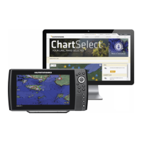
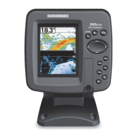
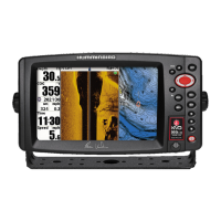
Instructions for connecting the data cable to compatible Humminbird control heads (ONIX/SOLIX, HELIX).
Steps for connecting the data cable to an Ethernet switch for network integration.
Procedures for performing mechanical checks before powering on the radar scanner.
Guidance on powering on the control head and initial setup for the radar.
Instructions on how to register the product and update software.
Details of the 2-year limited warranty, exclusions, and limitations.
Information about Humminbird's service policy for repairs and turnaround times.
Procedures for returning the unit for warranty or out-of-warranty service, including obtaining authorization.
Tasks recommended for yearly maintenance to ensure optimal product performance.
Instructions for cleaning the radar scanner unit.
Guidelines for storing the radar scanner unit properly.
Steps to resolve issues related to the radar scanner not connecting to the system.
Guidance on resolving discrepancies between displayed and true bearing readings.
Advice on addressing noise or other interference issues with the radar system.
List of regulatory approvals for the product in different regions like USA, Canada, EU, and Australia.
General specifications including voltage, power consumption, temperature ranges, and weight.
Technical specifications related to the radar transmitter, including type, frequency, and power output.
Technical specifications for the radar receiver, including IF bandwidth and noise figure.
Technical specifications for the radar antenna, including type, beamwidth, and rotation speed.
Diagram and measurements detailing the side view dimensions of the radar scanner.
Diagram and measurements detailing the rear view dimensions of the radar scanner.
Diagram and measurements detailing the underside view dimensions, including mounting hole locations.
| Brand | Humminbird |
|---|---|
| Model | CHIRP |
| Category | Radar |
| Language | English |