4
42699-01 • 06/30/10 • Hunter Fan Company
Preparing the Fan Site (continued)
CAUTION: All wiring must be in
accordance with national and local
electrical codes and ANSI/NFPA 70. If
you are unfamiliar with wiring, use a
qualied electrician.
Steps 2 – 3
Step 4
Step 5
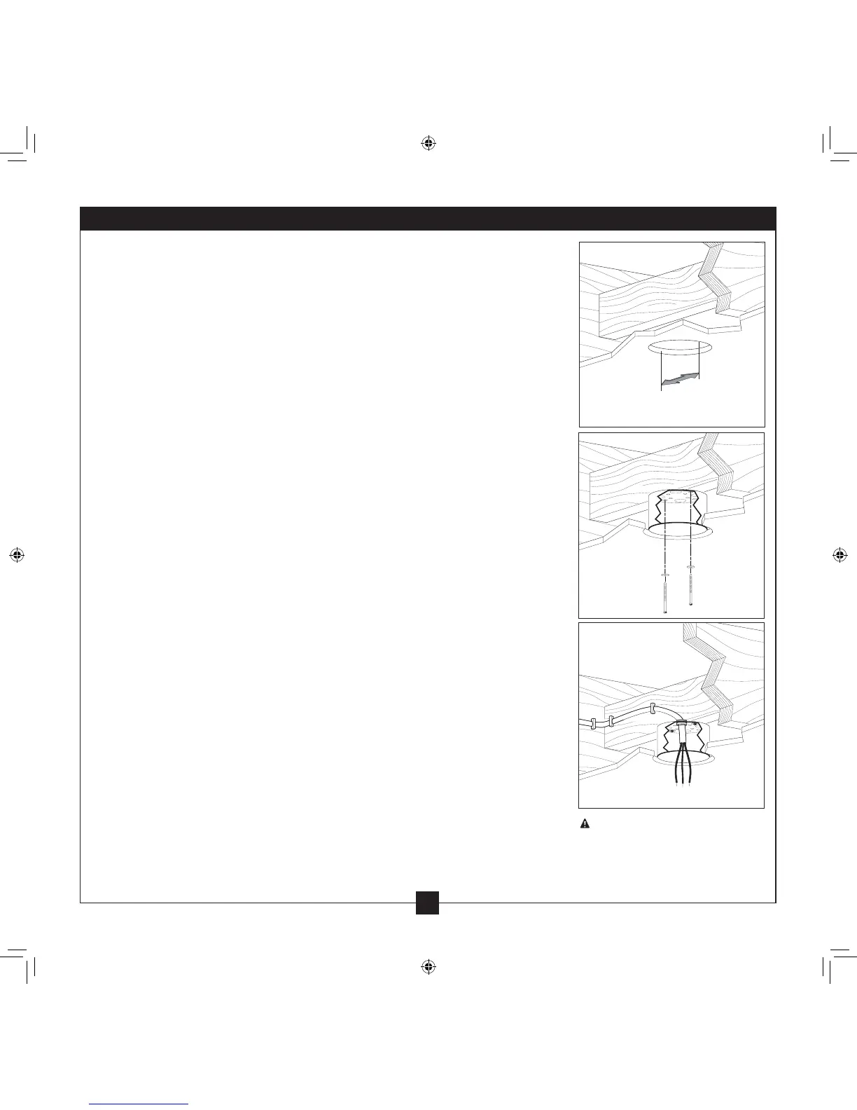
Step 2 - Cut the Ceiling Hole
2-1. Locate the site for the ceiling hole directly below the joist or support brace that
will hold the outlet box and fan.
2-2. Cut a 4” diameter hole through the drywall or plaster of the ceiling. You will use
the hole to install the support brace and outlet box.
Step 3 - Install a Support Brace, If Necessary
Determine if there is a ceiling joist directly above the ceiling hole. If the joist is there,
determine if it is positioned to allow you to recess the outlet box a minimum of
1/16” into the ceiling. If NOT, install a support brace as follows:
3-1. Attach a 2” x 4” support brace between two joists. Position it to allow you to
recess the bottom of the outlet box a minimum of 1/16” into the ceiling.
3-2. Check the support brace to ensure it will support the full weight of the fan and
light kit.
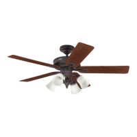
Step 4 - Install the Outlet Box
4-1. Obtain a UL-approved octagonal 4” x 1-1/2” outlet box, plus two #8 x 1-1/2”
wood screws and washers, available from any hardware store or electrical supply
house.
4-2. Orient the outlet box so that both the inner and outer holes in the box align
with the joist or support brace.
4-3. Drill pilot holes no larger than the minor diameter of the wood screws (5/64”)
through the inner holes of the outlet box.
4-4. Attach the outlet box directly to the support brace or joist with two #8 x 1-1/2”
wood screws and washers. e bottom of the outlet box must be recessed a
minimum of 1/16” into the ceiling.
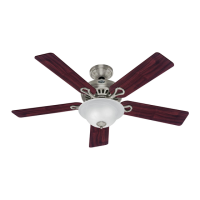
Step 5 - Prepare the Wiring
5-1. Make sure the circuit breakers to the fan supply line leads and associated wall
switch location are turned o . If you cannot lock the circuit breakers in the
o position, securely fasten a prominent warning device, such as a tag, to the
service panel.
5-2. read the fan supply line through the outlet box so that the fan supply line
extends at least 6” beyond the box.
5-3. Attach the fan supply line to the outlet box with an approved connector,
available at any hardware store or electrical supply house.
5-4. Make certain the wiring meets all national and local standards and ANSI/NFPA
70.
You have now successfully prepared your ceiling fan site. For instructions to install
your ceiling fan, go to your fan manual and continue with Section 2 • Installing the
Ceiling Plate.