This document is an installation manual for Hunter HVLS (High-Volume, Low-Speed) industrial ceiling fans. It provides comprehensive instructions for mounting, assembly, wiring, and maintenance, along with safety precautions and technical specifications.
Function Description
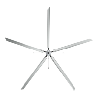
The Hunter HVLS fan is an industrial ceiling fan designed to move large volumes of air at low speeds, providing efficient air circulation and temperature regulation in large spaces. The fan is intended for professional installation and use in commercial and industrial environments. It features a robust design with various blade configurations (Titan, ECO, XP) to suit different needs and building structures. The fan system includes a motor, blades, downrod, control panel (VFD), and an HMI controller for operation. Guy wires are used for stability, and a retention cable ensures safety in case of mounting system failure. The system supports both single and multiple fan installations, with options for daisy-chaining controllers and integrating with fire alarm systems.
Important Technical Specifications
Fan Placement:
- Minimum clearance from floor to bottom edge of blade: 10 feet.
- Minimum clearance from ceiling to top of fan: 25% of fan diameter.
- Minimum clearance from any obstruction to blade: 2 feet.
- Sprinkler systems: Fans should be at least 3 feet below a sprinkler deflector and centered between 4 adjacent sprinklers.
- Walkways/Mezzanines: Blade tips must be at least 5 feet away from areas where a person could reach them.
- Lights/Skylights: Avoid mounting directly below to prevent strobe effect; maintain a minimum of 2 feet between blades and light fixtures.
- Air Discharge Locations: Not directly beneath vertical air discharge; outside swept area and at least two times the fan diameter for horizontal discharge.
- Not for outdoor or windy locations. Suitable for damp locations only.
Weight and Torque Considerations:
- Building structure must withstand approximately double (2x) the maximum hanging weight.
- 24' Titan: 212 lbs. hanging weight, 75 ft lbs. torque.
- 24' ECO: 150 lbs. hanging weight, 75 ft lbs. torque.
- 14' XP: 135 lbs. hanging weight, 75 ft lbs. torque.
Electrical Plug Requirements (Included Plug & Receptacle):
- Titan & ECO:
- 200-240V Single Phase: HBL2321 plug, L6-20R receptacle.
- 200-240V Three Phase: HBL2421 plug, L15-20R receptacle.
- 380-480V Three Phase: HBL2431 plug, L16-20R receptacle.
- XP:
- 110-120V: L5-15P plug, L5-15R receptacle.
Amp Draw and Breaker Size (Recommended):
- Titan:
- 24 ft: 8.2A (220V/1PH, 15A breaker), 4.3A (220V/3PH, 10A breaker), 3A (480V/3PH, 5A breaker).
- 20 ft: 7.2A (220V/1PH, 10A breaker), 4.0A (220V/3PH, 10A breaker), 2.6A (480V/3PH, 5A breaker).
- 18 ft: 7.8A (220V/1PH, 10A breaker), 4.1A (220V/3PH, 10A breaker), 2.4A (480V/3PH, 5A breaker).
- 16 ft: 7.2A (220V/1PH, 10A breaker), 3.8A (220V/3PH, 5A breaker), 1.8A (480V/3PH, 5A breaker).
- 14 ft: 5.4A (220V/1PH, 10A breaker), 2.8A (220V/3PH, 5A breaker), 1.2A (480V/3PH, 5A breaker).
- ECO:
- 24 ft: 6.3A (220V/1PH, 10A breaker), 2.6A (220V/3PH, 5A breaker), 2.3A (480V/3PH, 5A breaker).
- 20 ft: 5.5A (220V/1PH, 10A breaker), 2.9A (220V/3PH, 5A breaker), 2.1A (480V/3PH, 5A breaker).
- 18 ft: 4.9A (220V/1PH, 10A breaker), 2.6A (220V/3PH, 5A breaker), 2.0A (480V/3PH, 5A breaker).
- 16 ft: 5.6A (220V/1PH, 10A breaker), 2.8A (220V/3PH, 5A breaker), 2.2A (480V/3PH, 5A breaker).
- 14 ft: 4.5A (220V/1PH, 10A breaker), 2.4A (220V/3PH, 5A breaker), 2.0A (480V/3PH, 5A breaker).
- 12 ft: 4.6A (220V/1PH, 10A breaker), 2.4A (220V/3PH, 5A breaker), 1.8A (480V/3PH, 5A breaker).
- 10 ft: 4.7A (220V/1PH, 10A breaker), 2.4A (220V/3PH, 5A breaker), 1.9A (480V/3PH, 5A breaker).
- 8 ft: 2.7A (220V/1PH, 5A breaker), 1.4A (220V/3PH, 5A breaker), 1.2A (480V/3PH, 5A breaker).
- XP:
- 14 ft: 7.5A (110V, 10A breaker).
- 12 ft: 8.4A (110V, 15A breaker).
- 10 ft: 9.1A (110V, 15A breaker).
- 8 ft: 5.2A (110V, 10A breaker).
- 7 ft: 6.7A (110V, 10A breaker).
Mounting Configuration (Strut Channel):
- Channel Height 1 5/8": 12 GA (84' span), 14 GA (72' span), 16 GA (60' span).
- Channel Height 1 3/8": 12 GA (60' span).
- Channel Height 7/8": 12 GA (30' span).
- Channel Height 3 1/4": 12 GA (240" span).
- Channel Height 2 7/16": 12 GA (156" span).
Usage Features
Installation Process:
- Mounting: Secure bracket and downrod to an I-beam or strut channel, ensuring the building structure can withstand double the fan's weight. Use shims and clamps, tightening hardware with a 3/4" socket and wrench.
- Retention System: Wrap the retention cable around the building structure and secure it to itself with cable clamps. Leave approximately 3" of slack in the wire at the top of the downrod opening. Orient the U-bolt correctly to avoid crushing the wire.
- Motor Assembly: Align and connect the motor to the downrod, pushing cables into the downrod. Twist the connector collar to lock. Insert the retention link and clevis pin. Zip-tie the motor cable to the safety cable. Secure with nylon lock nuts using a 19mm deep socket or wrench.
- Control Panel (VFD): Mount the VFD control panel 5 feet outside the fan's swept area, with plug connectors facing down. Secure with four 1/4"-20 fasteners. Connect the VFD cable from the fan to the industrial control panel, twisting to lock. Connect the communication cable (Cat5) to a COMM terminal.
- Guy Wires (Titan & ECO Only): Attach beam clamps to the structure. Feed 15' guy wire through a Gripple and clip the 2' guy wire to the turnbuckle eyebolt. Feed the opposite end of the 2' guy wire through the same Gripple. Pull excess cable until taut. Use a level to ensure the downrod is plumb and the fan is level, then tighten turnbuckles in a crisscross pattern. Tighten bolts on Gripples and set screws on turnbuckles.
- Blades (ECO & XP): Insert press studs through blade holder holes, numbers facing up. Secure with nylon lock nuts using a 19mm wrench or socket.
- Blades (Titan): Line up the pin on the blade holder with the hub opening and insert until it clicks. Install the patch bolt and tighten until fully seated against the retention pin. Use a torque wrench to tighten the two set screws to 20 ft. lbs (240 in. lbs.), alternating 2-3 times for proper torque.
Network Configurations:
- Daisy Chain (350 & 500 Controllers): The Lead fan's VFD (labeled "Power") connects to the HMI from COMM 1. Subsequent fans connect from the Lead VFD's COMM 2 port to their COMM 1 ports using CAT5 cable.
- 700E Environmental Control: For zones less than 100 meters apart, the HMI connects to a Network Switch, which then connects to the Lead fan (FAN 1 IP.061 POE) via UP-LINK. Ceiling and floor sensors (IP.102, IP.101) connect to FAN 1. FAN 1's COMM 2 connects to FAN 2's COMM 1, and so on. For zones more than 100 meters apart, an additional Network Switch is used to connect the second zone.
- Powered vs. Non-Powered VFDs: Powered VFDs (Lead Fan VFD) have a white background on their connection port and must connect to the HMI controller. Non-Powered VFDs have a black background and cannot be the Lead Fan VFD or connect to the HMI controller directly.
Fire Panel Integration:
- Dry Contacts (Normally Closed): Remove jumper from "S" and "C" terminals on the VFD enclosure. Connect fire panel wires to "S" and "C".
- Normally Energized: Remove jumper from "S" and "C". Connect wire from "S" to "SA" and "C" to "C" on the Fire Relay Terminal Strip. Apply 12-40VDC from the Fire Panel to the Fire Relay Input (20mA draw).
- Normally Unenergized: Remove jumper from "S" and "C". Connect wire from "S" to "SB" and "C" to "C" on the Fire Relay Terminal Strip. Apply 12-40VDC from the Fire Panel to the Fire Relay Input (20mA draw).
- Multiple Fans: Fire relay arrangements for up to 30 fans are shown, with one VFD enclosure having the fire relay and others without.
Maintenance Features
Safety First:
- ALWAYS disconnect power (turn off circuit breaker, confirm Lockout/Tagout) before performing maintenance or service.
- If circuit breakers cannot be locked, securely fasten a warning device.
- Do not remove covers while power is on.
Blade Cleaning:
- Every 12 months, clean blades with a rag or sponge and hot water or regular cleaning solutions.
- DO NOT use chlorine or chemicals containing chlorine, as they may damage the blades.
Retention System Check:
- Every 12 months, inspect the retention cable for damage (e.g., fraying) and ensure it is properly attached to the building structure.
- The retention cable is a critical safety component.
Replacement Parts:
- Contact the Technical Department at 1-844-593-FANS (3267) for replacement parts.
Service:
- If the fan does not operate properly after following manual procedures, remove all power and contact the Technical Department at 1-844-593-FANS (3267).
Troubleshooting:
- Fan Will Not Start: Verify circuit breaker is on, VFD receptacle has power, VFD is plugged in, plug connections are secured, and wiring connections are tight.
- Motor Pulling Excessively High Amps: Ensure motor voltage matches supply voltage and correctly sized fan blades are installed.
- Fan Is "Swinging": Check for correct blade installation (same size, properly tightened), properly tensioned guy wires, plumb downrod, and no improper incoming air discharge directly on the fan.
- Fan Blade Appears "Sagging": Ensure the sagging blade has been properly tightened.