Do you have a question about the Hunter 28682 and is the answer not in the manual?
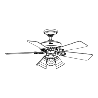
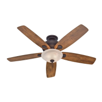
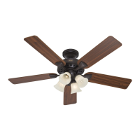
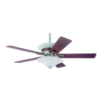
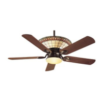
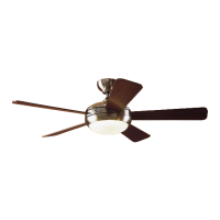
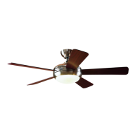
Welcome to your new Hunter ceiling fan, designed for comfort and performance.
Read the entire manual before installation and save instructions.
Use only Hunter replacement parts.
Connect fan directly to building structure using supplied hardware to reduce injury risk.
Disconnect power at circuit breakers before installation to prevent electric shock.
All wiring must comply with national and local electrical codes; use a qualified electrician if unfamiliar.
Do not bend blade brackets during installation, balancing, or cleaning to prevent injury.
Do not use fan with solid-state speed controls to prevent fire, shock, or motor damage.
Product conforms to UL STD 507 and is certified to STD C22.2 No.113.
Wash hands after installing the fan.
Choose a fan location ensuring clearance and proper support for safe, efficient operation.
Verify existing fan site suitability for a new Hunter fan installation.
Cut a 4" diameter hole in the ceiling for the support bracket and outlet box.
Install a 2" x 4" support bracket between ceiling joists if needed.
Secure an approved UL outlet box to the support bracket or joist with screws.
Ensure power is off, feed supply wire into outlet box, and connect to box with a connector.
Hunter's 3-position mounting system offers flexibility: Low Profile, Standard, or Angle Mount.
Consider optional Hunter accessories like wall or remote speed controls for enhanced functionality.
Connect fan directly to building structure using supplied hardware to reduce personal injury risk.
Ensure you can locate joists, drill holes, connect wires, and lift 40 lbs.
List of required tools for fan installation.
Unpack fan carefully and check for any shipping damage or missing parts.
Follow site preparation instructions for safe, efficient, and reliable fan operation.
Ensure power is off and breakers are locked out or tagged before starting installation.
Drill pilot holes through the outlet box's outer holes into the wood support.
Orient the ceiling plate so tabs point towards the highest point of the ceiling on sloped installations.
Verify that the four noise isolators are in place and undisturbed.
Place a flat washer on each of the two 3" wood screws.
Feed the power supply wires through the center hole of the ceiling plate.
Align the slotted holes and secure the ceiling plate using the pilot holes and screws.
Ensure proper assembly as per instructions to prevent the fan from falling.
Thread downrod through canopy, feed wires, and secure adapter set screw.
Do not remove adapter thread coating; it prevents downrod unscrewing.
Use low-profile canopy instead of downrod and remove adapter set screw.
Attach low-profile canopy using washer and three low-profile screws.
Lift fan, align canopy slots with ceiling plate hooks, and seat them securely.
Ensure all wiring complies with local/national codes; use a qualified electrician if unfamiliar.
Select a general-purpose wall switch that meets electrical codes.
Ensure the power supply remains off before starting wiring installation.
Connect wires by holding bare ends together and twisting on a plastic wire connector.
Connect ceiling, ceiling plate, and fan ground wires together.
Connect the ceiling white (grounded) wire to the fan white (grounded) wire.
Connect black ceiling wire to black fan wire, and black/white fan wire to switch.
Connect black ceiling wire to both black and black/white fan wires.
Ensure no bare or twisted wires are visible after making connections.
Tuck wire connectors upward into the outlet box.
Separate ground wires from ungrounded wires within the outlet box.
Failure to complete steps may cause the fan to fall.
Rotate suspension ball to secure tab in canopy slot for alignment.
Align canopy screw holes with mounting holes in the ceiling plate.
Partially install two screws, then the third, and tighten all firmly.
Verify that the canopy tabs remain engaged in the suspension ball slots.
Align trim ring tabs with slots and push firmly until it clicks into place.
Our exclusive Easy Lock system allows tool-free blade locking.
Align the holes in the fan blade with the blade iron posts.
Press the blade onto the three blade iron posts, ensuring posts are fully visible.
Repeat steps 6-1 and 6-2 until all fan blades are installed.
Clean blades with a dry or slightly damp, lint-free cloth; avoid abrasive cleaners.
Loosen blade iron posts with pliers and carefully remove the blade.
Use only the light fixture supplied with this fan model.
Partially install two box mounting screws to attach the lower switch housing.
Connect the motor's upper connector to the lower housing's connector.
Align notches, rotate housing clockwise to secure screws, and install third screw.
Adhere to maximum wattage limits on the bulb socket to prevent fire risk.
Install B10 candelabra bulbs (max 60 watts) into the sockets.
Pass light and fan pull chains through the glass shade and cover plate.
Thread decorative cover onto the threaded rod until snug.
Use the detachable connector to attach additional pull chains.
Use the fan pull chain for four speed settings: High, Medium, Low, and Off.
The light pull chain controls the lamp power with two settings: On and Off.
Rotate blades counter-clockwise for downdraft (cooling) in warm weather.
Rotate blades clockwise for updraft (heating) to circulate warm air.
Clean blades with a lint-free cloth; avoid waxes or abrasive cleaners.
Use a soft brush or lint-free cloth; mild detergent for stains.
Slide the reverse switch to the opposite position to change fan direction.
Check power, wiring connections, and ensure the motor reverse switch is set.
Tighten blade bracket screws and check for cracked blades.
Tighten blade screws, check suspension ball seating, use balancing kit if needed.
Verify bulb wattage, wait 5 minutes, then reset power.
Replace CFLs with dimmable bulbs or use in non-dimmable locations.
Contact Hunter Fan Company for parts or service, or visit their website.