7
8
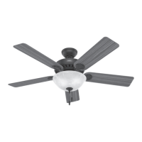
Ceiling Bracket Downrod Hanging Fan Wiring Canopy Blades Pull Chain
ON
Turn Power
Installing the Blades (CONT):
x6
x6
Repeat x6
bag
bag
Blade Screw
Blade Nut
Finish the blade installation by connecting the
previous blade arm connector to the current
blade’s trailing edge hole as shown using
the blade nuts and grommets, found in the
hardware bag, and the blade assembly
screws, found in the bag. Tighten ALL
blade screws.
x6
Grommet
Screw light kit screws from the
hardware bag halfway into
the motor housing. It does not
matter which two screw holes
you choose.
Feed the wire plug through the center
hole of the upper switch housing,
then wrap keyhole slots around the
screws and twist counterclockwise.
Insert a third screw, found
in the hardware bag,
into place and then tighten
all three screws.
1 of 3
Light Kit Screw
bag
2 of 3
Light Kit Screw
bag
1
STEP
2
STEP
3
STEP
FAN FALL HAZARD
Make sure all three screws are tight to secure
the upper switch housing to the mounting plate.
Connect the plugs from the upper and
lower switch housings. Make sure to line
up the colored markings on the connectors.
Lift the lower switch housing up until its
screw holes are aligned with the screw
holes in the upper switch housing.
Install the three switch housing screws
found in the hardware bag.
x3
Switch Housing
Screw
bag
4
STEP
5
STEP
6
STEP
FAN FALL HAZARD
Make sure all three screws are tight to secure the
lower switch housing to the upper switch housing
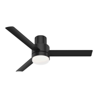
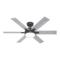
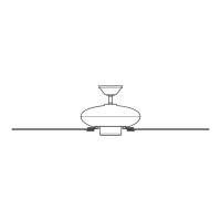
Fan style may vary.
Note:
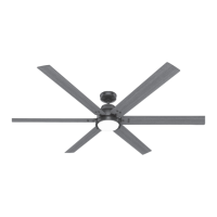
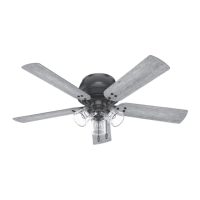
Fan style may vary.
Note:
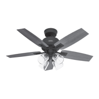
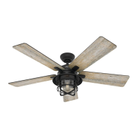
Fan style may vary.
Note: