8
Ceiling Bracket Hanging Fan Wiring Canopy Blades Light Glass Remote Troubleshooting Downrod
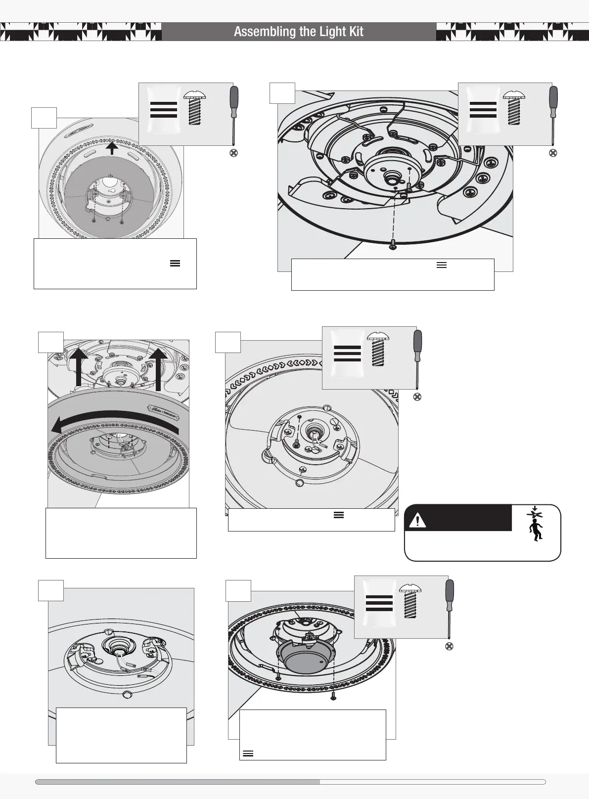
FAN FALL HAZARD
Make sure all screws are tight to secure
the light xture.
Insert the third screw, found in the hardware bag,
into place and then tighten all three screws.
Partially install two light kit screws, found in the hardware
bag, halfway into the motor housing as shown. It does not matter
which two screw holes you choose.
Lift the light kit and align the keyhole slots
with the two light kit screws. Feed the wires
through the center hole of the light kit, then
wrap keyhole slots around the screws and twist
counterclockwise.
Align the screw holes in the LED assembly with
the screw holes in the trim ring. Screw two LED
assembly screws, found in the hardware bag ,
through the LED assembly and into the trim ring.
1
STEP
2
STEP
3
STEP
4
STEP
2 of 7
Light Kit Screw
bag
2 of 7
Light Kit Screw
bag
1 of 7
Light Kit Screw
bag
Connect the wires from the LED assembly
to the wires from the fan. Connect the
white wire to the white wire. Connect
the blue wire to the black wire. Tuck the
excess wiring above the LED assembly.
5
STEP
Raise cap to the LED assembly. Align the
notches on the sides of the cap with the screw
holes in the LED assembly. Install the two LED
assembly screws which can be found in the
hardware bag.
6
STEP
2 of 7
Light Kit Screw
bag