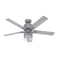
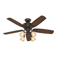
Step 9: Aligning the Fixture Fitter
A.
Assemble the fixture fitter to the fitter mounting plate by
inserting the upper plug connector through the hole in the center
of the fitter and securing the fitter to the mounting plate using
(3) 3/8" long phillips round head screws with lockwashers.
Tighten the (3) screws securely. See Figure 9.
CAUTION: Failure to securely tighten the (3) assembly screws
could result in the light kit falling.
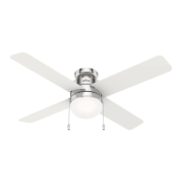
B. Plug the upper and lower plug connectors together. Attach
the light fixture to the fitter using (3) 3/8" long phillips round
head screws with lockwashers. Tighten the (3) screws securely.
See Figure 9A.
CAUTION: Failure to securely tighten the (3) assembly screws
could result in the light fixture falling.
Install (2) lamps. Refer to maximum wattage label on the light
fixture for maximum lamp wattage.
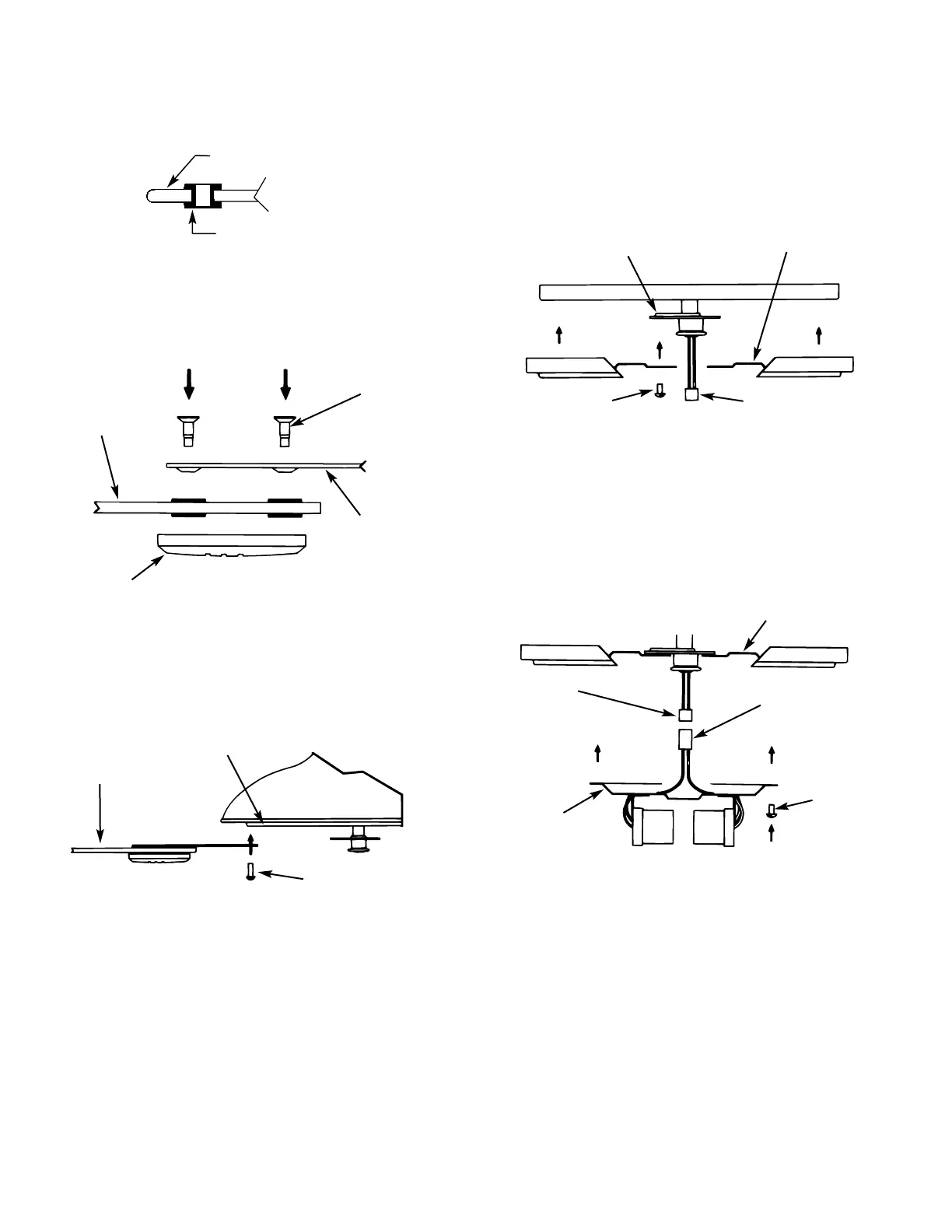
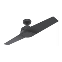
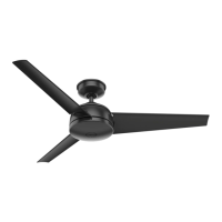
Step 8: Fan Blade Assembly,
Installation, and Balancing
A.
First insert the rubber grommets into the (3) holes in each
wood blade. See Figure 8.
B. Next assemble the wood blades to the sheet metal blade
brackets and blade medallions using (3) shoulder screws for each
blade. See Figure 8A. Make sure all screws are tight.
C. Attach each blade assembly to the blade mounting plate at
the bottom of the fan using (2) #10-32 x 1/2" long phillips round
head screws with lockwashers. See Figure 8B. Tighten the
assembly screws securely.
Repeat the step until all blades are securely attached.
D. A blade balancing kit has been provided with your fan.
Should the fan wobble in operation, you may use the kit to cor-
rect the balance per the instructions supplied with the kit.
NOTE: After installing all the blades, check the (10) blade
bracket assembly screws which attach the brackets to the motor.
Make certain they are tight. See Figure 8B.
41228-01 12/95 - 5 - ©1995 HUNTER FAN CO.™
Figure 8
Figure 8A
Figure 8B
SHOULDER
SCREWS
SHEET METAL
BLADE BRACKET
WOOD BLADE
BLADE ASSEMBLY
BLADE MOUNTING PLATE
BLADE
BRACKET
ASSEMBLY
SCREWS (10)
MEDALLION
Figure 9
Figure 9A
FITTER MOUNTING PLATE
FIXTURE FITTER
ASSEMBLY
SCREWS
UPPER PLUG
CONNECTOR
ASSEMBLY
SCREWS
LOWER PLUG
CONNECTOR
UPPER PLUG
CONNECTOR
LIGHT
FIXTURE
FITTER
GROMMET
BLADE