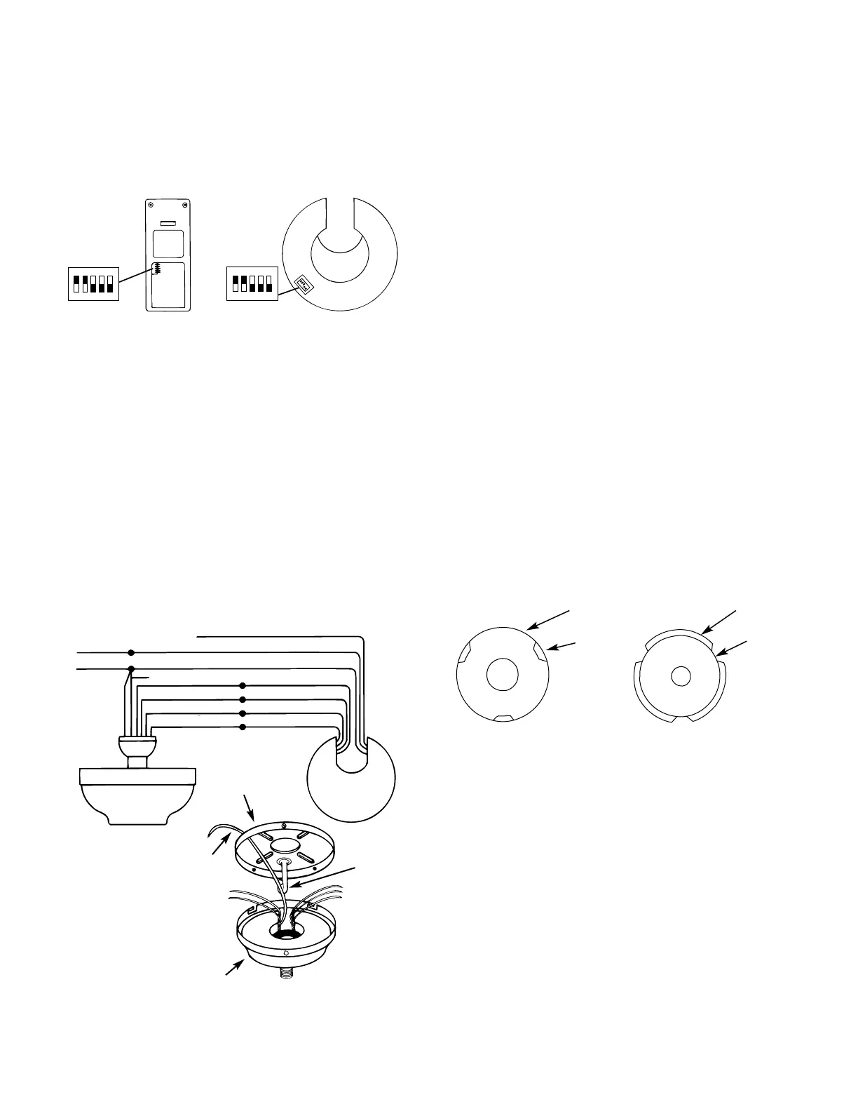
IMPORTANT! Before installing this control make sure the posi-
tion of the dip switches of the transmitter and receiver are
matched. If they are not matched, the control will not function.
Select different combinations of dip switches for each fan instal-
lation in the house to prevent interference of one control with
another. See Figure 6.
IMPORTANT! When you change dip switches, make sure the
battery is not connected to the transmitter.
A. Install a fresh 9-volt battery into the transmitter (battery not
supplied).
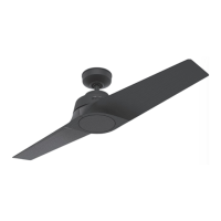
Place the receiver inside the canopy. First make sure the oval
shaped holes in the bottom of the receiver and dip switches are
facing down, toward the bottom of the canopy. Spread the
receiver lead wires to each side and feed the wires from the top
of the fan through the open slot in the receiver. Now place the
receiver into the canopy making sure the slot in the receiver is
aligned with the hook in the ceiling plate. When properly
installed the hook in the ceiling plate will fit inside the open slot
of the receiver. If the hook and slot do not line up with each
other, rotate the receiver until the two parts align. The canopy
can not be attached to the ceiling plate unless the hook is posi-
tioned in the receiver slot.
B. Connect electrical supply leads from the motor, using
approved connectors. Connect the yellow from the fan to the yel-
low from the receiver, pink from the fan to the pink from the
receiver, grey from the fan to the grey from the receiver and the
black with white tracer from the fan to the black with white trac-
er from the receiver.
Connect the red and white wires from the fan with the white
from the receiver to the white power (common) wire. Connect
the larger black wire from the receiver to the black power wire.
Run the thin white antenna wire from the receiver through one of
the slots in the ceiling plate and outside the canopy (when
installed). See Figure 6A.
Connect the ground wire to the green lead wires from the ceiling
plate and the hanger ball.
After wiring is completed, check all connections to ensure that
they are tight and there are no bare wires visible at the wire
connectors.
CAUTION: No bare wire or wire strands should be visible after
making connections.
C. After making the wire connections, the wires should be
spread apart with the white and green wires on one side of the
outlet box and the other wires on the other side of the outlet box.
The splices should be turned upward and pushed carefully into
the outlet box.
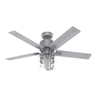
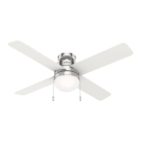
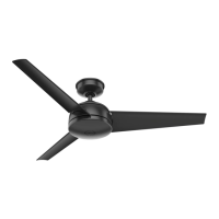
Step 7: Finish Hanging Fan
A.
Remove the fan from the ceiling plate hook. Make sure you
do not break any wire connections. The canopy has (3) suspen-
sion flanges located on top. See Figure 7. The ceiling plate has
(3) mating slots. See Figure 7A.
B. Lift the fan and position the (3) flanges in the canopy into
the (3) mating slots in the ceiling plate. Lift the fan until it is free
to rotate in either direction. Rotate the fan until the (3) holes in
the canopy line up with the (3) mating holes in the ceiling plate.
Using (3) 10-32 x 1/2'' long Phillips round head screws, secure
the canopy to the ceiling plate.
CAUTION: Check and make sure no wires are caught between
the canopy and ceiling plate.
CAUTION: Failure to properly tighten the (3) screws could
result in the fan falling.
NOTE: For the ball hanging fan configuration make sure the (2)
grooves in the ball are engaged with the (2) tabs in the canopy.
Failure to do so could result in the fan falling. See Figure 5C.
41228-01 12/95 - 4 - ©1995 HUNTER FAN CO.™
CANOPY
CEILING
PLATE
SLOT
FLANGE
Figure 7 Figure 7A