Step 5-2: Ball Hanging Version
CAUTION: Do not lift motor by wires.
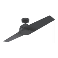
A. Insert pipe nipple through canopy and feed wires from top
of motor through pipe nipple. Screw pipe nipple into fan until
tight (at least 4-1/2 turns). The setscrew locking the pipe nipple
to motor must be tightened very securely. See Figure 5B.
Failure to tighten screw could result in fan falling.
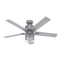
B. Before hanging the fan from the ceiling plate align and
engage the (2) tabs in the bottom of the canopy with the (2)
grooves in the hanger ball. See Figure 5C.
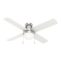
Using the round hole in the top of the canopy, hang the fan from
the hook in the ceiling plate. Make sure both tabs in the canopy
remain engaged with the grooves in the ball. Be careful and
don’t scratch the finish while hanging the fan. See Figure 5A.
Step 6: Install Remote Control
and Final Wiring
CAUTION: This device complies with part 13 of the FCC rules.
Changes or modifications not expressly approved by Hunter Fan
Company could void your authority to operate this equipment.
Operation is Subject to the Following Two Conditions:
(1) This device may not cause harmful interference.
(2) This device must accept any interference received, including
interference that may cause undesired operation.
NOTE: Use with a fan that incorporates an air gap switch (nor-
mal “ON-OFF” wall switch).
WARNING! Maximum fan load is 100 watts; maximum lamp is
240 watts. Do not use any speed control with this product.
Step 5-1: Fan Assembly
Low Profile Version
A.
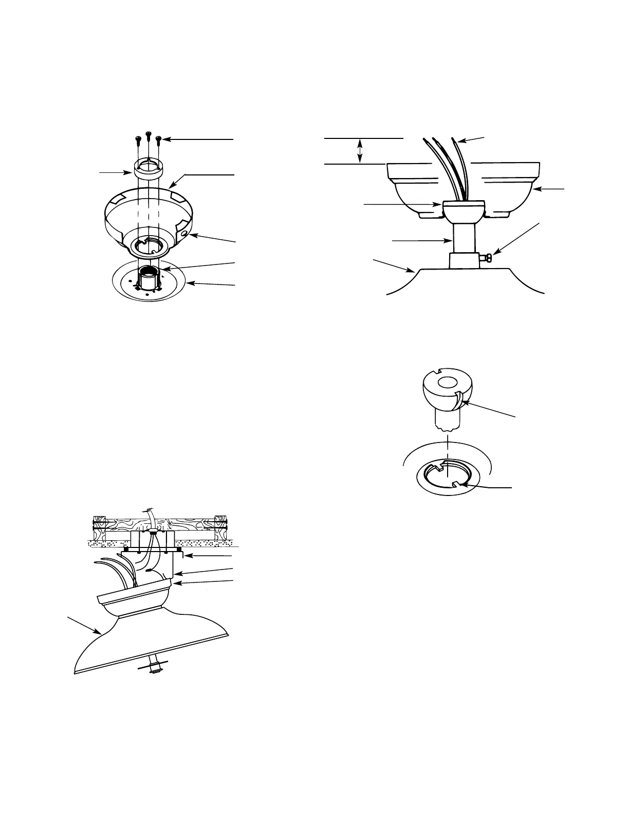
Place the canopy on top of the fan so the hole in the bottom
of the canopy fits over the adaptor on the top of the fan. See
Figure 5. Place the canopy assembly washer inside the canopy
with the vertical flange of the washer resting on the inside of
the canopy.
B. Position the (3) slots in the canopy assembly washer over
the (3) threaded holes in the adaptor. See Figure 5.
C. Secure the canopy to the top of the fan using the (3) #8-32
x 7/8 long screws with lock washers. Make certain all screws
ae tight. Failure to do so could result in the fan falling.
CAUTION: To ensure proper engagement of the canopy assem-
bly screws, the canopy must fit snug against the top of the fan.
CAUTION: Do not lift motor by wires.
D. Being careful not to scratch the canopy finish, hang the fan
from the hook in the ceiling plate using the round hole in the
top of the canopy. See Figures 5 and 5A.
41228-01 12/95 - 3 - ©1995 HUNTER FAN CO.™
Figure 5. Low Profile Version
Figure 5B
ASSEMBLY
WASHER
#8-32 SCREW
CANOPY
ROUND HOLE
LEAD WIRES
PIPE
NIPPLE
BALL
PIPE NIPPLE
MOTOR
SETSCREW
(TIGHTEN
SECURELY)
CANOPY
ADAPTOR
TOP OF FAN
Figure 5A. Hanging the Fan
FAN
CEILING PLATE
HOOK
CANOPY
Figure 5C. Aligning Tab & Groove
GROOVE IN
HANGER BALL
TAB IN BOTTOM
OF CANOPY
6" MIN.