11
41847-01 • 08/12/09 • Hunter Fan Company
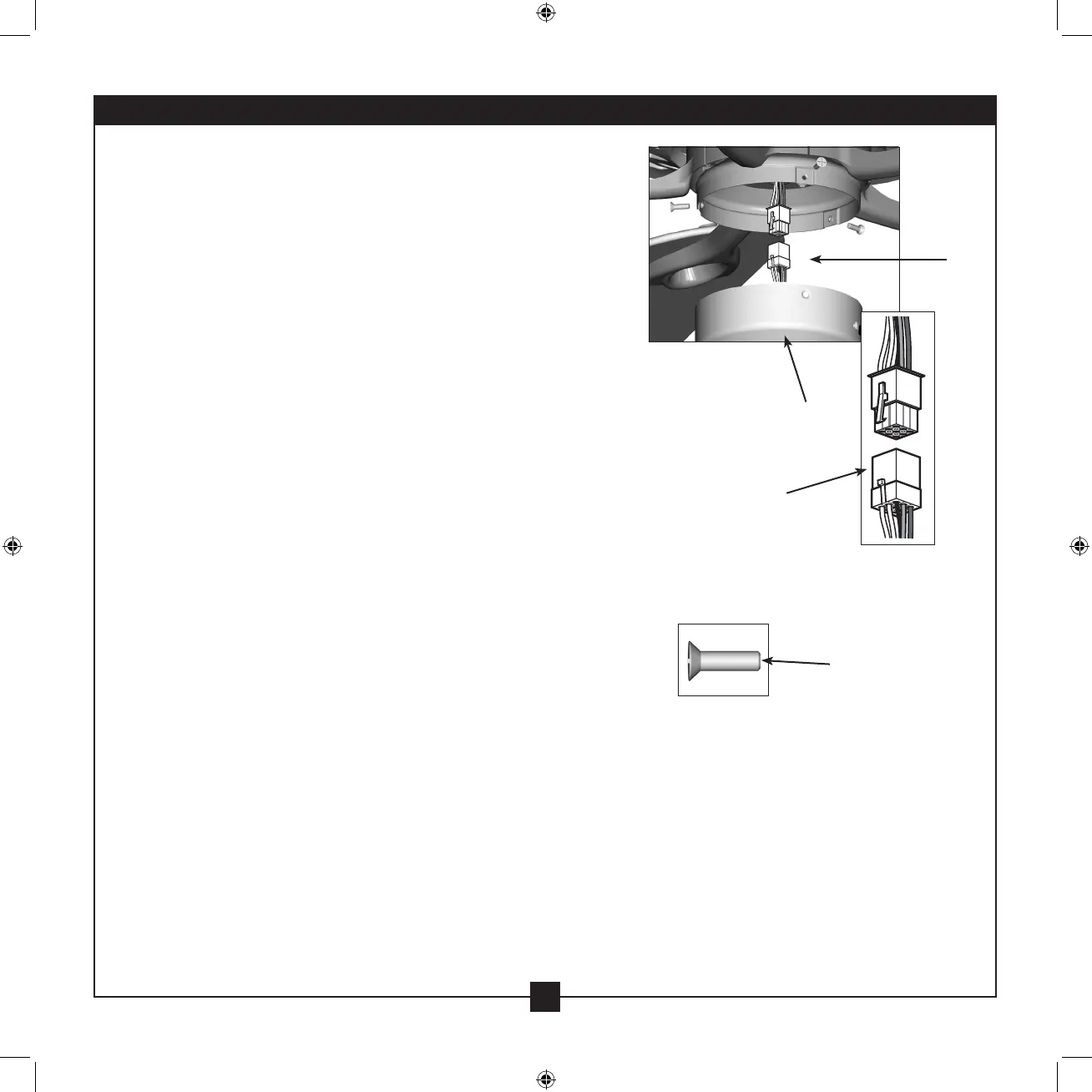
Lower Switch
Housing
Plug
Connector
Housing
Assembly Screw
Plug
Connector
Detail
Steps 7-6 – 7-7
7-6. To attach the lower switch housing, connect the upper plug
connector from the motor to the lower plug connector in the
lower switch housing assembly.
Note: Both plug connectors are polarized and will only t together
one way. Make sure the connectors are properly aligned before
connecting them. Incorrect connection could cause improper
operation and damage to the product.
7-7. Place the lower switch housing assembly over the upper switch
housing. Align the side screw holes in the upper and lower switch
housings. Attach the lower switch housing to the upper switch
housing with three housing assembly screws.
If you are not installing the light fixture, your installation is
complete. Otherwise, proceed with step 7-8.
7-8. e last installation step when installing the light xture is to
install the glass bowl. See “Installing the Glass Bowl” on page 13 for
instructions.
7 • Completing Your Installation With or Without a Bowl Light Fixture (Continued)