Do you have a question about the HURNER HST 300 Junior + 2.0 and is the answer not in the manual?
Ensures proper connection terminal compatibility with fittings and secure contact for safe operation.
Details on handling cables, avoiding carrying the unit by them, or pulling the power cord.
Instructions on securing fittings and joints using clamps or a vice before welding.
Specifies that the product should not be sprayed with or immersed in water.
Advises that only authorized personnel should open the product cover.
Guidelines for using approved extension cables with specified conductor sections and proper deployment.
Emphasizes pre-use checks of safety features, connections, and parts for proper function.
Advises compliance with product maintenance indications for safe work.
Covers requirements for mains and generator power supplies, including fuse protection.
Service and repair must only be performed by manufacturer or authorized partners for safety.
Product should be stored and shipped in its original transport box to protect it.
Steps to power on the welding unit after connecting to a power source and initial display.
Guidance on connecting terminals to the fitting, ensuring clean contact surfaces and proper fit.
Procedure for scanning fitting bar codes to input welding parameters, including confirmation.
Initiating the welding process using the START/SET key after parameter input and confirmation.
Description of the welding process monitoring, displaying voltage, resistance, and current.
Successful completion criteria for the welding process, indicated by nominal welding time and buzzer.
Identifying an aborted process via error messages and acknowledging with the STOP/RESET key.
Respecting fitting manufacturer's instructions for cooling time, displayed and counted down.
Resetting the unit to the parameter input stage after welding or via the STOP/RESET key.
Accessing abstracted welding reports, including report number, date, time, and parameters.
Procedure for manually inputting welding voltage and time using arrow keys and START/SET.
Process for manually entering the 24-character fitting code, with error checking.
Accessing technical info like software version, serial number, and next maintenance date.
Explains resistance measurement, comparison to code, and error indication if tolerance is exceeded.
Describes the unit's response to high transformer temperature, aborting welding.
Message indicating previous welding aborted due to power supply issues, and how to proceed.
Guide to selecting the display language from options like Deutsch, English, and Français.
Instructions for setting the date and time using the keypad and confirming settings.
Adjusting the volume of the status buzzer using arrow keys and confirming the setting.
Options for temperature units (C/F) and entering the unit's inventory number.
Covers errors like Code Error, No Contact, Low Voltage, Overvoltage, and Overheated during data entry.
Details errors occurring during welding, including Low Voltage, Overvoltage, Resistance, Frequency, Voltage, Current, Emergency Off, Heater Coil, and Power Supply Failure.
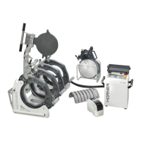
| Brand | HURNER |
|---|---|
| Model | HST 300 Junior + 2.0 |
| Category | Welding System |
| Language | English |