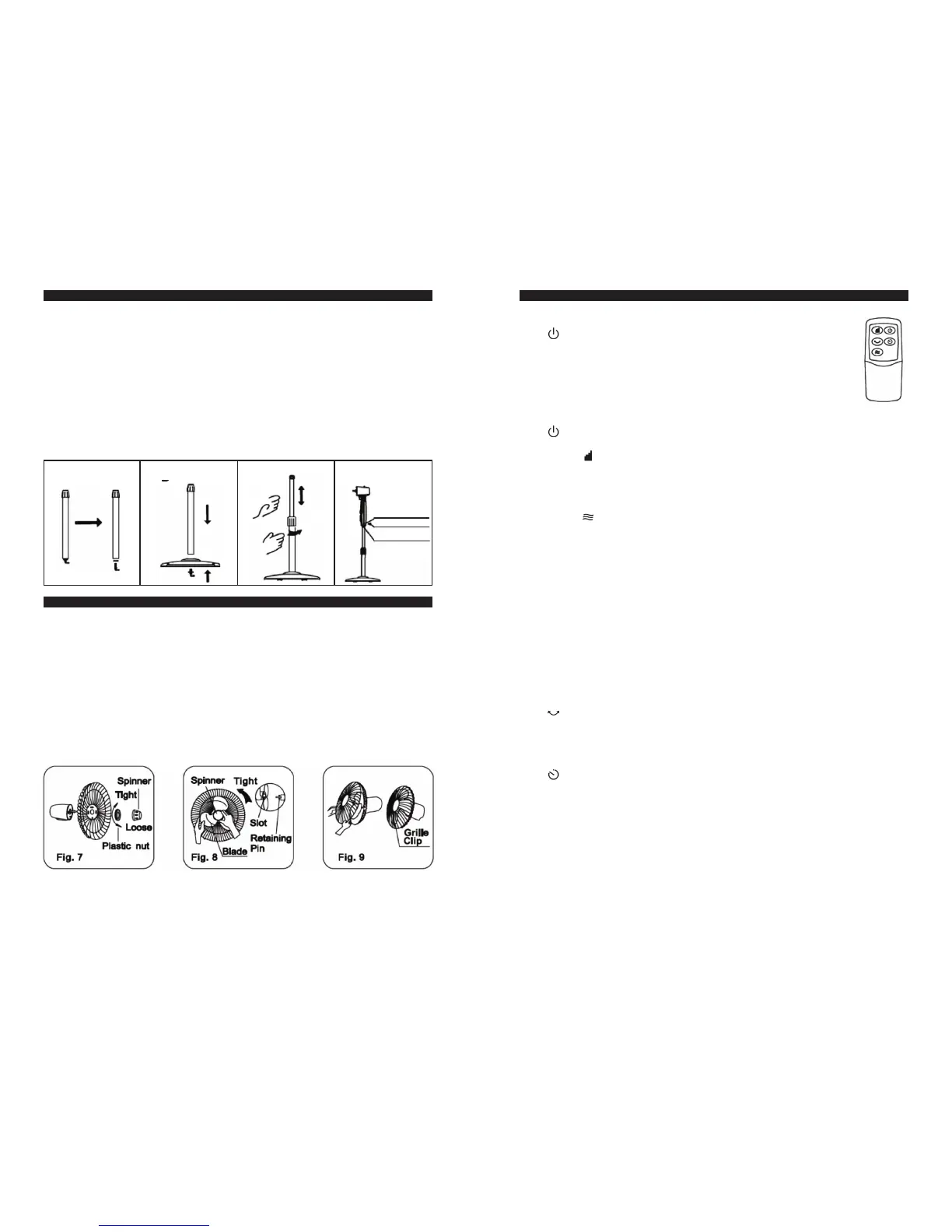
ROUND BASE & COLUMN UNIT ASSEMBLY
1. Take the chassis and internal/external upright tube assemblies out of the
packing carton, and screw off the chassis lock nut at the bottom. (See Fig. 1)
2. Align the upright tube bottom with a hole on the chassis, and tighten the
chassis lock nut according to the drawing. (See Fig. 2)
3. Unscrew the external connector, adjust the internal upright tube to a
proper height (Note: if there is no upright tube, the internal upright tube
may slide into the external upright tube, and can be pulled out). Screw in
the external connector. (See Fig. 3)
4. Unscrew the fastening bolt at the bottom of the head, put the head on
the internal upright tube, alight the fastening bolt with the ring-shaped
groove at the top of the internal upright tube, and tighten the fastening
bolt. (See Fig. 4)
GUARD & FAN BLADE ASSEMBLY
1. Take the Spinner out from the bag, then remove the plastic nut by
turning it counterclockwise.
2. Place the rear guard to the head unit make sure the handle is upward.
3. Screw on the plastic nut (clockwise) securing the fan guard on the the
head unit. (Step 1,2,3 see Fig.7)
4. Discard the small plastic sleeve located on the motor shaft.
5. Install the fan blade onto the motor shaft. Make sure the fan blade slot
fits into the retaining pin of the motor shaft. (Step 4,5 see Fig.8)
6. Attach the spinner to the motor shaft by turning it counterclockwise to
secure the fan blade.
7. Secure both guards firmly by tightening the fan guard then close easy
clips. (Step 7 see Fig.9)
Fig. 1
Bolt mounting hole
Loosen
Fig. 3
Fastening bolt
Ring shaped groove
OPERATING INSTRUCTION
I. Remote Control (Fig. 10)
1. CONTROL KEY
• “
” ON KEY
After the plug is inserted, the buzzer gives one sound, and
the fan is in standby. Upon this key being pressed, the fan
works for 3s at normal wind of Level 2 and enters normal
wind mode of Level 1, the indicator illuminating and wind
speed being Level 1. After power-on, the characters for room
temperature and functions (TIMER, OSC, WIND MODE and
WIND SPEED ) will illuminate.
• “
” OFF KEY
When the fan is running, press this key to turn off the fan.
• WIND “
” SPEED KEY
When the fan starts, this key is pressed repeatedly, wind speed changes
in the order of “1-2-3”, and wind speed displays a corresponding level.
Normal wind, natural wind and sleep wind have three levels of wind
speed. Fig.10
• WIND “
” MODE KEY
This key is provided to select air supply mode, and if it is pressed repeat-
edly, wind type will change cyclically in the sequence of “Normal Wind –
Sleep Wind – Natural Wind”, and on the screen a corresponding indica-
tor will show the wind type of the fan. The three types of wind have the
following features:
Normal wind: the fan will deliver wind constantly according to the
wind speed level set by the wind speed key, wind speed having three
levels
Natural wind: the fan will simulate natural wind according to the com-
puter pre-programming, and delivered wind speed is to change based
on the program, making people feel fresh and natural. Depending on
speed setting, the natural wind has three levels of speed.
Sleep wind: the fan will simulate natural wind according to the com-
puter pre-programming, having three levels of wind speed. The deliv-
ered wind is light and soft.
• “
” OSC KEY
If after the fan starts, this key is pressed repeatedly, the fan will oscillate
and deliver wind according to the sequence of “Left/Right – Up/Down –
‘8’ shape – fixed direction”. Corresponding indications are shown on the
control panel, but there is no indication for air supply of fixed direction.
• “
” TIMER KEY
The timing function can set the fan to shut up automatically after 0.5-8
hour.
Timing OFF: if this key is pressed after power-on, the 0 and first 0.5h
bar graph on the timing plate illuminate, entering 0.5h timing. When
this key is pressed repeatedly, the bar graphs on the timing plate will
illuminate in turn clockwise, each bar graph showing 0.5h. Figures on
the timing plate also illuminate in turn clockwise, indicating how many
hours have been preset. After timing process is set, bar graphs on the
timing plate will go out every 0.5h in turn counterclockwise, and each
of the figures on the timing plate will also extinguish every 1h in turn
counterclockwise until timing countdown reaches 0 to shut up. After
completion of timing setting, press any key to increase the timing pe-
riod, which will continue countdown based on the finally set time.
Fig. 10
 Loading...