DEALER / INSTALLER
Provide a copy of these instructions to the end user of this product. These instructions provide
important operating and safety information for proper usage of this product. Demonstrate the
proper use of the product with the end user. Have the end user demonstrate that they understand
the proper use of the product.
END USER
Read and follow all instructions included in this manual. Ask your Dealer/Installer for assistance if
you do not understand the proper use of the product. Never remove any decals from the product.
Failure to follow these instructions can result in injury or death.
TOOLS & COMPONENTS REQUIRED
A-FRAME COUPLER WITH LOWER SUPPORT PLATE (SEE FIGURE 6)
THREE (3) GRADE 5, 1” LONG, 3/8”-16 UNC BOLTS (INCLUDED)
THREE (3) 3/8” FLAT WASHERS (INCLUDED)
THREE (3) 3/8” STAR WASHERS (INCLUDED)
9/16” WRENCH
TORQUE WRENCH
WIRE CUTTERS
WIRE STRIPPERS
CRIMPERS OR SOLDERING IRON
PART
NUMBER
87247, 87248,
87641 & 88141
INSTALL
TIME
30 MINUTES
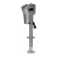
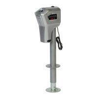
SPECIFICATIONS
MODELS APPLICABLE HB3000; HB4500; HB4500R
MAXIMUM LIFT CAPACITY 3,000 LB / 4,500 LB (CONTINUOUS USE)
RETRACTED HEIGHT 31-3/8”
VERTICAL TRAVEL 18”
POWER REQUIREMENTS 12 VOLT DC
OUTER TUBE DIAMETER 2-1/4”
POWER CORD LENGTH 6 FT OF #10 GAUGE WIRE
FOOT PAD DIAMETER 5-1/2”
LED WORK LIGHTS ON 3 SIDES FOR EASY NIGHTTIME HOOKUPS
SHIPPING WEIGHT HB3000 – 27-1/2 LB; HB4500 & HB4500R – 29 LB
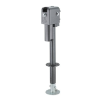
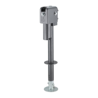
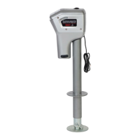
BRUTE ELECTRIC TRAILER JACK
(
HB3000, HB4500 & HB4500R
)
WITH SMART STOP
Assembly, Installation, Operation, and Maintenance Instructions
See www.huskytow.com for Warranty Information / Tech Support / Product Updates.
©2023 Keystone Automotive Operations Inc. All Rights Reserved. September 2023. REV1 Page 1 of 7