SAFETY EQUIPMENT
GB
12 – English
1. First remove the following components:
• Chain and guide bar. See instruction book.
• Centrifugal clutch. See page 22.
Chain brake
Dismantling
!
WARNING!
Check that the chain brake is in the on
position. If it is not, the pressure spring
can fly up causing personal injury.
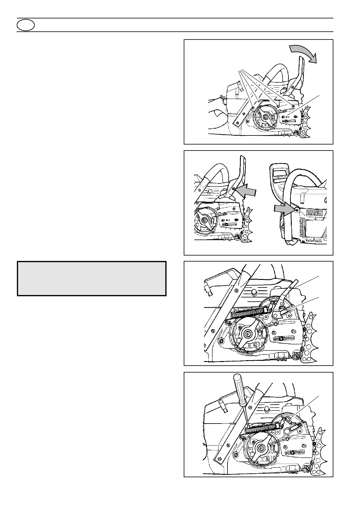
Fig. 1
Fig. 2
Fig. 3
Fig. 4
A
B
D
C
E
2. Push the hand guard forward so that the chain brake is
on. See fig. 1
3. Unscrew hand guard, two bolts. Note sleeving on the
starter side. See fig. 2.
4. Remove bolt (A) and chain guide-plate. See fig. 1.
5. Undo the four bolts (B) and remove the chain brake
assembly cover. See fig. 1.
6. Press down the retaining bush (C) and remove the lever
arm (D). See fig 3.
7. Remove the pressure spring by freeing the rearward end
with a screwdriver. See fig 4.
8. Remove the toggle joint (E) with attached brake-strap.
See fig 4.
9. Disconnect the brake-strap from the toggle joint.
10.Take out the retaining bush (C) and spring. See fig 3.
For Husqvarna Parts Call 606-678-9623 or 606-561-4983
www.mymowerparts.com