PN_3155541_C U.S. & Canada 1-800-922-1919 • Mexico 1-800-890-2900 • www.hussmann.com
42 sErvIcE
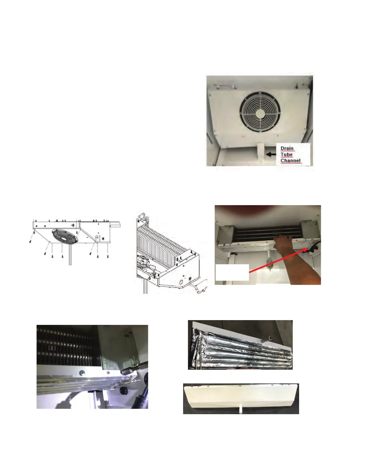
Remove screws from Fan Plenum. See gure for
screws location and drain tube channel. See Figure A
Tilt the fan plenum to access to the evap. fan harness
connection as well as the light switch.
Identify and disconnect the evap. fan harness.
Remove Fan plenum. See Figure B
Identify evap. pan heater leads. See Figure C.
Disconnect heater leads from harness
Pass heater leads through bushing.
Unscrew hexagonal head screws in order to release
the evaporator pan assembly. See Figure E.
See Figure F for the evaporator pan assembly example.
Remove aluminum foil and old wire heater.
See Figure G, which shows the sheet metal pan.
Evap Fan
Harness
Figure D
Figure C
Figure E
Figure F
Figure G
1.
2.
3.
4.
5.
6.
7.
8.
9.
10.
REPLACING EVAPORATION PAN HEATER
Drain
Tube
Channel
Evap Fan
Harness
Figure B
Figure D
Figure C
Figure E
Figure F
Figure G
Drain
Tube
Channel
Evap Fan
Harness
Figure B
Figure D
Figure C
Figure E
Figure A
Figure B
Drain
Tube
Channel
Evap Fan
Harness
Figure B
Figure D
Figure C
Figure C
Figure D
Figure E
Figure F
Figure G
Note: This procedure applies to all VRL models
(1-door model is shown in the photos)