REV D 3-4 604466
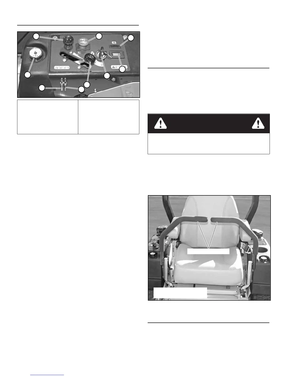
Control Panel
When access is required under the seat platform and the seat
is equipped with the optional arm rests, make certain to place
the control arms in the park brake position and pivot the arm
rests upward before placing the seat platform in the full forward
position to prevent arm rest damage.
A. Deck clutch switch (Figure 3-1) — th
is switch engages
the deck. Pull the switch up to engage and push switch
dow
n to disengage the clutch.
IMPORTANT: For additional clutch information r
efer
to the Mower deck operation section of this manual.
B. Ignition switch (Figure 3-1) — a
three position switch:
“OFF”, “RUN”, and “START”. With key inserted, rotate
it clockwise to “ST
ART” position; release key when
engine starts, and switch will automatically return to the
RUN position.
C. Oil pressure light and alarm (Figure 3-1) — th
is light
comes on when the ignition switch is place
d in the RUN
position and stays lit until the engine is running and a
safe oil pressure is developed. If light comes on during
operation, shut engine off immediately and locate and
correct the problem.
An audi
ble alarm will sound when the engine oil pressure
drops below normal operating pressure.
D. Throttle control (Figure 3-1) — a
cable is linked to the
engine throttle for controlling engine speed. Move lever
forward to increas
e engine rpm, move lever rearward to
decrease engine rpm.
E. Choke control (Figure 3-1) — a
cable is linked to
manually operate the engine choke. When the lever
is in
the down position, the choke is in the off (run) position.
When the knob is pulled up, the choke is in the on (start)
position. Do not operate the machine in the on (start)
position.
F. Electronic hour meter (Figure 3-1) — regi
sters 1/10
hour increments up to 9,999.9 total hours. Connected to
the ignition s
witch, the meter records the accumulative
time while the ignition key is switched to the RUN
position.
G. 10 amp fuse (Figure 3-1) — Igni
tion system - 10 amp,
blade-type.
H. 15 amp fuse (Figure 3-1) — Safet
y system - 15 amp,
blade-type.
I. Fuel tank gauge (Figure 3-1) —
This gauge shows the
fuel level for each fuel tank.
Controls
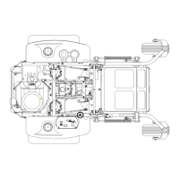
A. Steering control levers (Figure 3-2 & Figure 3-3) —
these levers control the mower’s speed, direction,
stopping,
and park brake. These levers are used to steer,
accelerate, decelerate and change direction. When the
steering control levers are in the park brake position the
mower will not move when the engine is on and drive
pumps are operating.
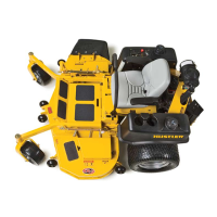
B. Deck lift pedal (Figure 3-4) —
the deck lift pedal is used
to raise or lower the deck. Push on the pedal to raise the
deck
and then place the deck height locking pin into the
desired cutting height hole.
Push the deck lift pedal to raise the de
ck when going over
obstructions.
Safety Start Interlock System
The mower is equipped with a safety start interlock system
consisting of the park brake switches, seat switch, and deck
clutch switch.
Check the mower’s safety start interlock system daily
,
prior to operation. This system is an important mower safety
A. Deck clutch s
witch
B. Ig
nition switch
C. Oil pressure
light
D. Thro
ttle
E. Chok
e
F. H
our meter
G. Fuse
H. Fuse
I. Fuel
gauge
Figure 3-1
The parking brake may not hold the mower if parked on a
slope. Block or chock the machine when parked on a
slope.
Figure 3-2
Shown with steering control
levers in neutral position
Steering control lever

 Loading...