Do you have a question about the Huvitz CAB-4000 and is the answer not in the manual?
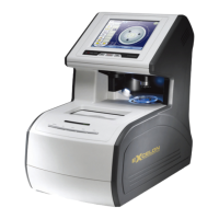
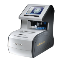
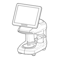
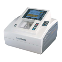
Describes the physical components and layout of the Auto-Blocker CAB-4000.
Outlines the general flowchart for diagnosing and repairing the device.
Lists important warnings and precautions for safe operation and handling.
Displays current software and hardware version details.
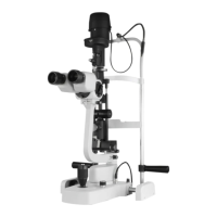
Explains the configuration and components of the optical system.
Details the scientific basis and method for lens measurement.
Overview of the main calibration screen options.
Procedures for calibrating the lensmeter function, including modes like Live Image, LM Mode, and setup options.
Steps for calibrating the blocking position and related functions like image processing.
Calibration process for the frame tracing module, covering stroke, frame, and pattern.
Instructions for simulating tracer calibration using the Tracer-Sim menu.
Troubleshooting guide for resolving a specific prism setup error message.
Guidance on handling a common startup warning message by contacting support.
Detailed steps to calibrate the lens blocking position accurately using a cross marker.
Procedure to calibrate the rotational axis for blocking lenses, adjusting for misaligned angles.
Steps to calibrate the optical center of the internal lensmeter for accurate PD/optic height.
Procedure to calibrate the rotational axis of the internal lensmeter for optic lens accuracy.
Steps to recalibrate the touch screen for accurate input by touching screen corners.
Covers various maintenance tasks, such as fuse replacement and checking specifications.
Instructions for disassembling the outer casing of the device by removing screws.
Step-by-step guide to remove the LCD screen assembly and its related components.
Procedure for removing the front panel of the unit, detailing screw and component removal.
Guide to removing the tracer, image camera, and inner cover modules from the device.
Instructions for removing other key internal modules like blocking arm and lensmeter.
Steps to remove the power supply, GUI board, and motor board assemblies.
Guide to removing sensors located within the blocking arm assembly.
Instructions for disassembling the blocking theta axis assembly, including grip components.
Diagrams and identification of components on the main Printed Circuit Board assembly.
Diagrams and identification of components on the motor control Printed Circuit Board.
Troubleshooting flowchart for the Switched-Mode Power Supply (SMPS) module.
Diagnostic steps for testing the LCD display functionality and brightness.
Procedure for testing the image camera module, checking for image display and brightness changes.
Steps for testing the lensmeter camera, ensuring proper image display and measurement.
Troubleshooting steps for when the power indicator LED does not turn on.
Diagnostic steps for the touch screen interface, checking buzzer feedback and calibration.
Overview of the firmware update process and requirements for the Auto-Blocker.
Detailed guide on using the DNW application for OS upgrades via serial or USB connection.
| Brand | Huvitz |
|---|---|
| Model | CAB-4000 |
| Category | Laboratory Equipment |
| Language | English |