Do you have a question about the Huvitz HPE-810 and is the answer not in the manual?
Details the primary functions of the lens processing system, including tracing to edging.
Describes the possible system configurations involving the Edger, Frame Reader, and Blocker.
Details the device's classification regarding FCC rules and safety standards.
Emphasizes the importance of safety and understanding manual instructions for all users.
Explains the meaning of various safety symbols used on the instrument and its labels.
Lists environments to avoid for operation or storage to ensure proper machine performance.
Provides detailed safety precautions for operating, maintaining, and repairing the equipment.
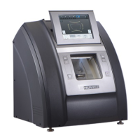
Provides a front and internal view of the Edger unit, highlighting key components.
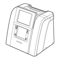
Illustrates the front and rear views of the Frame Reader, identifying its main parts.
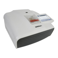
Shows the front and bottom views of the Blocker, detailing its operational controls.
Lists and illustrates the standard accessories included with the equipment.
Provides step-by-step instructions for installing the Edger unit, including connections.
Details the installation steps for the Frame Reader, including initial power-on and connection.
Outlines the installation procedure for the Blocker, focusing on power connection.
Explains the operation of the Frame Reader, including its control panel and tracing functions.
Covers the operation of the Blocker, including scale plates, lens adapter setter, and blocking modes.
Describes the basic controls of the Edger, such as START, STOP, WINDOW, and CLAMP buttons.
Provides an overview of the Edger's main screen layout and navigation elements.
Explains how to manage jobs, including creating new jobs and using the virtual keyboard.
Details the information displayed for a frame, such as curve, circumference, and diameter.
Describes options for setting up lens layout, including PD, bridge size, and frame material.
Explains various edging options like edging type, grooving parameters, and bevel settings.
Covers detailed edging settings such as feeling, clamp pressure, and wrap removal.
Describes the function buttons available on the interface, including Expert Job Editor and Retouch Mode.
Explains how to manually adjust bevel and groove positions for precise edging.
Details how to select specific regions on the lens shape for adjustment.
Describes methods for modifying lens position, including global and partial adjustments.
Explains the functionality of the Reset and Apply buttons for saving or discarding changes.
Details the screen used for partial grooving operations, including region and processing type selection.
Explains how to define the start and end points for partial grooving on the lens shape.
Covers the selection of different processing types for partial grooving, including combinations.
Describes the options for activating front and rear safety bevels.
Explains the reset and apply functions for partial grooving settings.
Details the Job Manager interface for selecting, managing, and processing jobs.
Explains the function buttons within the Job Manager, such as Open, Save, Search, and Delete.
Describes the 'Waiting Job' list, showing details of jobs received from other devices.
Details the 'Working Job' list, showing the status of jobs currently being processed.
Describes the 'Completed Job' list, showing finished jobs and their processing states.
Explains how to search for specific jobs within the system using the virtual keyboard.
Covers the Digital Pattern feature for modifying lens shapes for rimless and semi-rimless frames.
Explains how to adjust the near vision area of the lens shape.
Details how to rotate the lens shape using touch interface and value input.
Describes how to modify specific parts of the lens shape.
Explains how to reset the lens shape to its original form.
Describes the function for synchronizing right and left lens shape data.
Explains how to exit the Digital Pattern mode and return to the main screen.
Details the Retouch Mode for fine-tuning lens shape, size, polishing, and grooving.
Covers the Hole Editor for defining hole positions for drilling, including blocking mode settings.
Describes the elements at the top of the Hole Editor screen, including navigation buttons.
Explains the working area of the Hole Editor, showing frame and hole/slot details and editing tools.
Details the preview function in the Hole Editor for viewing holes/slots and copying them.
Explains the various function buttons for hole/slot editing, such as grouping, mirroring, and deleting.
Shows the list of holes/slots, allowing changes to coordinate display and group creation.
Details the properties of selected holes/slots, including group ID, diameter, depth, and drilling angle.
Introduces the Job Editor for comprehensive access to all edging options, useful for skilled users.
Lists and explains various edging options configurable within the Job Editor.
Details the steps involved in starting the edging process after setting options.
Describes the edging screen interface, including status icons and processing states.
Explains how to stop the edging process at any time using the STOP button.
Covers how the system handles errors, including pop-up messages and process stops.
Describes the completion of the edging process, including sounds and messages, and how to remove the lens.
Explains the function for registering and processing frame change lens data.
Details how to activate Frame Change Mode and its implications for lens processing.
Outlines the procedure for performing a frame change, including data transmission and guideline checks.
Explains how to configure the Frame Reader, including user options like ID, Beep, and port settings.
Guides on accessing the Edger's configuration menu, including preferences, adjustments, and software versions.
Details how to adjust various edging-related options to fine-tune processing quality.
Explains the process for automatic calibration of the Frame Reader, covering stroke, frame, and pattern.
Details the automatic calibration procedures for Edger size and feeler settings.
Introduces Test Mode for verifying the proper functioning of machine components and sensors.
Explains the importance and procedure of wheel dressing to maintain wheel performance.
Covers how to view statistical information about processed lenses and wheel usage.
Explains how to set the system date and time.
Details how to perform a touch screen test to check its operational status.
Describes how to backup, restore, or reset system configuration data.
Explains the process for upgrading the system's GUI and MOTOR software.
Mentions the use of a maintenance code for system diagnosis by engineers.
Provides essential maintenance tips, including wheel and drill bit replacement cycles.
Recommends regular maintenance cycles and procedures for maintaining performance.
Details the fuse specifications and replacement procedure for the Edger and Frame Reader.
Provides instructions for cleaning the product, including precautions for the exterior and LCD.
Lists all standard accessories provided with the Edger system.
Provides detailed technical specifications for the Edger, Frame Reader, and Blocker.
Includes technical drawings and dimensions for the Edger system.
| Polishing | Yes |
|---|---|
| Power Supply | AC 220V, 50/60Hz |
| Edging Material | Polycarbonate, High-index, Trivex |
| Beveling | Automatic |
| Grooving | Automatic, Manual |
| Safety Beveling | Automatic, Manual |