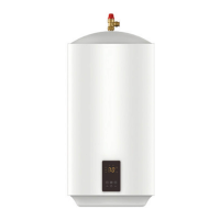
HYCO POWERFLOW SERIES UNVENTED ELECTRIC STORAGE WATER HEATERS
1. INTRODUCTION & TECHNICAL SPECIFICATION
Thank you for purchasing a POWERFLOW Series Unvented Electric Storage Water Heater from Hyco Manufacturing Ltd.
To use this equipment safely please read this manual carefully. When the unit is installed, the operation and maintenance
section should be explained to the user of the equipment.
Do not proceed with installation or operation if there is sign of any damage to the product or the power cord.
If you have any queries regarding operation or installation please contact our technical department on 01977 517555.
READ THESE INSTRUCTIONS BEFORE ATTEMPTING INSTALLATION.
INSTALLATION MUST BE UNDERTAKEN BY A COMPETENT INSTALLER TRAINED IN THE INSTALLATION
OF UNVENTED WATER HEATING SYSTEMS IN ACCORDANCE WITH BUILDINGS REGULATION G3.
BUILDING REGULATION G3 REQUIRES A TEMPERATURE AND PRESSURE RELIEF VALVE TO BE FACTORY
FITTED. THIS MUST NOT BE REMOVED OR BLOCKED IN ANY WAY.
INSTALLATION MUST COMPLY WITH THE LATEST EDITION OF THE IEE WIRING REGULATIONS.
THESE UNITS ARE VERY HEAVY. THEY MUST BE SECURELY FASTENED TO A SUITABLY STRONG WALL
USING THE FIXINGS SUPPLIED. REMEMBER TO ALLOW FOR THE WEIGHT OF THE WATER (ONE KG PER
LITRE OF CAPACITY) WHEN ASSESSING THE SUITABILITY OF THE WALL.
2. SPECIFICATIONS
3. INSTALLATION OVERVIEW
THIS UNIT MUST BE INSTALLED VERTICALLY, WITH THE PIPES POINTING DOWNWARDS AND THE
TEMPERATURE AND PRESSURE RELIEF VALVE AT THE TOP.
1
Model PF30L PF50L PF90L
Maximum water pressure to pressure reducing valve 12 bar
Power (kW) 3.0
Voltage (V) 230V ~ 50 Hz
Current (A) 13A
Capacity (Litres) 30 50 90
Operating Pressure 3 bar
Expansion vessel charge pressure 3 bar
Expansion relief valve setting 6 bar
Pressure Reducing Valve setting 3 bar
Temperature and Pressure Relief 7 Bar 90 degrees C
Minimum recommended pressure 0.8 bar
Immersion heater specifi cation Hyco PFEL30 EN60335 x 1
Weight empty (kg) 9 13 24
Weight full (kg) 39 63 114
Heat up time (from 13°C to 60°C) in minutes 21 40 86
Reheat time (70% contents to 60°C) in minutes 16.5 28 57
Height (mm) 620 915 930
Width (mm) 380 380 540
Depth (mm) 295 295 385
Tank Material Stainless steel
Inlet / Outlet ½ ” BSP male
Components Checklist
✔
Expansion Vessel 3/4" MBSP, precharge pressure 3.5 bar
6
13. MAINTENANCE - ANODE INSPECTION (Continued)
It is not normally necessary (or practical) to attempt to remove any scale from the tank walls.
Refi t element and follow commissioning instructions as per section 8.
14. MAINTENANCE - SAFETY VALVE CHECKS
The Temperature and Pressure relief and expansion relief valve relieve any dangerous pressure or temperature build up that
may arise as a consequence of abnormal operation.
BOTH valves should be tested periodically by twisting the cap and checking that water fl ows freely.The water fl ow should
cease when the valve is released.
The pressure reducing valve contains a wire mesh gauze that may become clogged over time.To clean, close off mains water
and open a hot outlet to drain the system of water.
Unscrew the plastic top of the pressure reducing valve from the brass housing and remove complete mechanism including
wire mesh. Rinse mesh to remove grit, scale etc as necessary and replace.
Re-commission system following instructions as per section 8.
15. MAINTENANCE – EXPANSION VESSEL
Water expands when it is heated.The expansion vessel accommodates expanded water during the heating cycle via a
pressurised diaphragm arrangement so that water is not wasted.
The vessel is supplied already pressurised to 3 bar.Over time the pressure may be lost and water may be discharged during
the heating cycle.
The pressure should be checked using a standard car tyre foot pump or similar device. The pressure should be re-set to 3 bar.
16. TROUBLESHOOTING
Symptom Likely Fault(s) Remedy
Water not heating Thermal cut-out needs re-setting Reset as section 11.
Element failure Replace
Thermostat failure Replace
Thermal cut-out failure Replace
Electrical supply failure Check supply is present
Water too hot Thermostat set too high Reduce setting
Fit thermostatic mixing valve
Water milky coloured Dissolved gases coming out of solution as they are heated –
this is normal condition for pressurised systems
No action needed. Water will
turn clear after standing for a
few seconds.
Water discharged during
heating cycle only
Expansion vessel has lost its charge Re-pressurise vessel as section
15.
Water discharged all the
time
Either the pressure reducing valve is failing to reduce the
water pressure to 3 bar approx, or one of the safety valves
is operating at below is nominal level.
To differentiate measure the water pressure downstream
of the pressure reducing valve. If the pressure is more than
about 4 bar, replace the pressure reducing valve.
If the pressure is less than 4 bar, replace the safety valve
that is opening.
Replace appropriate valve.
No / limited water fl ow Check mains water is turned on. Check pressure reducing valve
for grit.
Mixing valves not working
correctly
Unbalanced pressure. Ensure cold is tee-ed off after
pressure reducing valve so hot
and cold are at equal pressure.
 Loading...