EasyManua.ls Logo

Hyd-Mech S-20 A User Manual

Hyd-Mech S-20 A
80 pages
To Next Page IconTo Next Page
Page #1 background imageLoading...
Page #1 background image
1
S-20/23 A
395427
January 2006 Revision A
THANK YOU,
On behalf of everyone at HYD
.
MECH, I would like to thank and congratulate you on your decision to purchase a HYD
.
MECH band saw.
<RXUQHZPDFKLQHLVQRZUHDG\WRSOD\DNH\UROHLQLQFUHDVLQJWKHHI¿FLHQF\RI\RXURSHUDWLRQKHOSLQJ\RXWRUHGXFHFXW-
ting costs while boosting quality and productivity.
To ensure you are maximizing the power and versatility of your new HYD
.
MECH band saw, please take the time to famil-
iarize yourself and your employees with the correct operation and maintenance procedures as outlined in this manual.
:HVLQFHUHO\DSSUHFLDWHWKHFRQ¿GHQFH\RXKDYHGHPRQVWUDWHGLQSXUFKDVLQJRXUSURGXFWDQGORRNIRUZDUGWREXLOGLQJD
ORQJDQGPXWXDOO\EHQH¿FLDOUHODWLRQVKLS
Thank-you.
HYD
.
MECH GROUP LIMITED
P.O. BOX 1030, 1079 Parkinson Road
Woodstock, Ontario Canada, N4S 8A4
Phone: (519) 539-6341
Service 1-877-237-0914
Sales 1-877-276-SAWS(7297)
Fax (519) 539-5126
e-mail: info@hydmech.com

Table of Contents

Question and Answer IconNeed help?

Do you have a question about the Hyd-Mech S-20 A and is the answer not in the manual?

Hyd-Mech S-20 A Specifications

General IconGeneral
BrandHyd-Mech
ModelS-20 A
CategorySaw
LanguageEnglish

Summary

SECTION 0 - SAFETY INSTRUCTIONS

Summary and Basic Rules

Summary of safety instructions and rules for safe machine operation.

Owner Responsibilities

Owner's duties regarding manual accessibility, personnel, and machine condition.

Operator and Maintenance Responsibilities

Personnel responsibilities for safety equipment, procedures, and hazard awareness.

FOREWORD

Put Safety First!

General emphasis on safety and hazard consideration before performing any action.

Signatures

Operation Signatures

Confirmation of understanding safety and operating instructions by operators.

Installation and Maintenance Signatures

Confirmation of understanding by installation and maintenance personnel.

BASIC RULES

Intended Use and Liability

Machine design for intended use and disclaimer of liability for misuse.

Responsibilities of the Owner

Work Organization and Personnel Management

Manual accessibility, personnel qualification, and training requirements.

Defining Roles and Workplace Condition

Defining responsibilities and ensuring proper machine and workplace conditions.

Operator and Maintenance Personnel Responsibilities

Safety Equipment and Procedures

Verification of safety equipment, emergency stops, and operational safety rules.

Labels, Clothing, and PPE

Importance of safety labels and guidelines for clothing and personal protective equipment.

Personal Safety Guidelines

Gloves and Hearing Protection

Precautions for wearing gloves and requirements for hearing protection.

Workplace Requirements

Maintaining a clear, unobstructed, and well-lit work area for safe operation.

Lockout and Residual Risks

SECTION 1 - INSTALLATION

Initial Inspection and Safety Precautions

Inspection for shipping damage and general safety precautions for installation.

Operator Safety Rules

Specific safety rules for the machine operator during installation and operation.

Handling and Removal from Skid

Forklift Lifting Procedure

Instructions for safely lifting the saw using a forklift truck.

Shipping Wrap Removal and Skid Removal

Steps for removing shipping wrap and safely removing the saw from its skid.

Installation Setup Procedures

Levelling, Hydraulic Oil, and Cutting Fluid

Procedures for levelling the saw and filling hydraulic oil and cutting fluid.

Power Wiring Connections

Instructions for safe electrical connections by qualified personnel.

SECTION 2 – OPERATING INSTRUCTIONS

Blade Basics and Break-in

Information on blade technology, proper break-in, and maintenance for longevity.

Sequencer Control Overview

Overview of the sequencer control console and its three main groups of controls.

Panel Mounted Controls

Vise and Head Selector Switches

Operation of the Front Vise, Head, and Shuttle Vise selector switches.

Cycle Start and Emergency Stop Buttons

Functionality of the Cycle Start/Pause and Emergency Stop pushbuttons.

Additional Operator Controls

Blade Start/Stop Controls

Controls for starting and stopping the blade motor.

HMI Key Functions

Explanation of HMI keys: Function, Numeric, Navigation, Back, and Enter.

Display and Indexing Cycles

Display Interface and Screens

Explanation of the display interface, special screens, and screen map.

Single and Multi Indexing Cycles

Detailed explanation of Single Indexing and Multi Indexing cycle types.

Operating Modes

Manual Mode Operation Guide

Step-by-step guide for operating the machine in Manual Mode.

Single Cut Mode Operation Guide

Procedures for using the Single Cut Mode to cut a single part.

Automatic Operation Modes

Auto Mode Overview and Setup

Overview of Auto Mode and entering the mode for job setup.

Automatic Job Programming Procedures

Steps for editing or starting a new job in Automatic Mode.

PLC 100 Control System

Operation Overview

Explanation of the PLC's role in manual and automatic machine operation.

PLC Control Modes and Functions

Manual Mode Only Controls

Description of controls available exclusively in Manual Mode.

Manual & Auto Mode Controls

Description of controls available in both Manual and Automatic Modes.

Machine and Cycle Controls

Auto Mode Activation and Controls

Activating Auto Mode and associated control functions.

Machine Start and Cycle Management

Controls for starting the machine and managing cycles (Start, Pause).

Automatic Job Management

Automatic Operation Setup and Job Entry

Entering Auto Mode and setting up jobs for automatic processing.

Editing and Starting Jobs in Auto Mode

Procedures for editing existing or starting new jobs in Automatic Mode.

Queue Operation

Working with a Standard Queue

Running multiple jobs sequentially using the QUEUE function.

Working with a Repeating Queue

Setting the QUEUE parameter to repeat a sequence of jobs.

Cutting Adjustments and Mechanical Controls

Kerf Correction for Angle Cutting

Adjusting for kerf value differences in mitered cuts for accuracy.

Head Swing and Brake Adjustment

Adjusting the head swing angle and securing it with the angle brake.

Head Limit and Coolant Controls

Head Up Limit Setting Procedure

Adjusting the head's upward travel limit to reduce cycle time.

Coolant System Controls

Controls for managing flood and mist coolant systems.

Guide Arms and Cutting Parameters

Guide Arm Positioning Adjustment

Adjusting guide arms for optimal blade life based on material width.

Shuttle Length Controls and Chart Reference

Encoder function for cut lengths and reference to the cutting parameters chart.

Hydraulic Feed Control

Cutting Setup Example #1

Step 1: Determine Effective Material Width

Method for determining the effective material width for cutting setup.

Step 2: Set Feed Force Limit

Setting the maximum feed force limit for the head descent.

Blade Pitch and Speed Determination

Step 3: Determine Optimum Blade Pitch

Selecting the correct blade pitch (TPI) for optimal cutting rates.

Step 4: Determine Optimum Blade Speed

Using a graph to determine the optimum blade speed based on material.

Feed Rate Setting Determination

Step 5: Determine Feed Rate Setting

Determining the correct feed rate (FR) using graphs and calculations.

Cutting Setup Examples and Pitch Adjustments

Optimum vs. Actual Blade Pitch Factors

Table and factors for adjusting feed rate based on blade pitch.

Additional Cutting Setup Examples

Examples demonstrating cutting setup procedures for different materials.

SECTION 3 – MAINTENANCE AND TROUBLESHOOTING

Maintenance Safety and Lockout Procedures

Safety precautions during maintenance and the lockout procedure.

Restoring Machine to Use

Procedures for safely returning the machine to operation after maintenance.

Blade Handling and Tracking

Blade Changing Procedure Steps

Step-by-step guide for changing the saw blade, including safety.

Blade Tracking Adjustment Process

Process for inspecting and adjusting blade tracking for proper wheel alignment.

Blade Guide Adjustment

Brush, Brake, and Limit Switch Adjustments

Blade Brush Adjustment Method

Adjusting the blade brush for optimal cleaning of blade gullets.

Angle Brake Adjustment Procedure

Procedure for adjusting the angle brake for secure head positioning.

Head Down Limit Switch Adjustment

Adjusting the head down limit switch for proper cut completion.

Lubrication Points and Recommendations

Gearbox Lubrication

S-20A Gearbox Lubrication Details

Lubrication requirements and oil type for the S-20A gearbox.

S-23A Gearbox Lubrication Details

Lubrication requirements and oil type for the S-23A gearbox.

Hydraulic Maintenance and PLC System Overview

Hydraulic System Maintenance Procedures

Procedures for maintaining the hydraulic system, including filters and oil.

PLC System Overview and Battery

Overview of the PLC system, its inputs, and battery replacement.

PLC Parameters and Definitions

PLC 100 Troubleshooting - Length Measurement

Problem #1: PLC Not Measuring Lengths

Troubleshooting steps for issues where the PLC is not measuring lengths.

Troubleshooting Length Accuracy Issues

Problem #2: Inaccurate Lengths in AUTO Mode

Troubleshooting inaccurate lengths when operating in AUTO mode.

Diagnosis and Inconsistent Inaccuracy

Diagnosing length issues and specifically addressing inconsistent inaccuracies.

Troubleshooting Length Inaccuracies

Consistent Inaccuracy Causes

Identifying causes of consistent length inaccuracies, such as blade kerf.

Linear Inaccuracy Correction

Correcting linear length inaccuracies by adjusting PLC parameters.

PLC Cycle Sequence and Fuse Issues

Auto Cycle Sequence Logic

Understanding the sequence of inputs and outputs during an automatic cycle.

PLC Fuses and No Display Troubleshooting

Information on PLC fuses and troubleshooting a 'No Display' issue.

PLC Display Troubleshooting and I/O

Problem #5: No Blade Speed Display

Troubleshooting steps for a missing blade speed display.

Mitsubishi PLC Inputs and Outputs

Identification of Mitsubishi PLC inputs, outputs, and status indicators.

PLC Calibration and Terminal Information

Input/Output Terminal Identification

Detailed identification of PLC input and output terminals.

Length Calibration Procedure

Procedure for calibrating length control parameters like ACTUAL LENGTH.

SECTION 4 - ELECTRICAL

Main Panel Component Layout

Visual layout of electrical components within the main panel.

PCB Board Fuse Location

Main Panel Connections and PLC Identification

Main Panel Electrical Components

Safety Relay and Fuse Locations

Electrical Schematic Drawing Numbers

SECTION 5 - HYDRAULIC

Hydraulic Component List

List of hydraulic components with part numbers and descriptions.

Hydraulic System Component Locations

Filler Cap and Filter Element Location

Location of the filler cap, filter element, and cleanout cover.

Oil Level Gauge and Drain Plug Location

Location of the oil level gauge and drain plug on the hydraulic unit.

SECTION 6 - MECHANICAL ASSEMBLIES

SECTION 7 - OPTIONAL EQUIPMENT

Out of Stock Switch Function

Function of the out of stock switch in preventing cycle continuation.

Mist Coolant System Operation

Operation and adjustment of the mist coolant system.

Optional Equipment Details

Variable Vise Pressure Adjustment

Adjustment of vise clamping pressure and its effects on clamp speed.

Overhead Bundling System Operation

Ensuring efficient operation of the overhead bundling system.

Work Stop and Lamp Assemblies

Work Stop Assembly Identification

Identification of the work stop assembly.

Work Lamp Assembly Details

Details of the work lamp assembly.

SECTION 8 - SPECIFICATIONS

S-20A Bandsaw Specification List

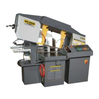
Detailed specifications for the S-20A bandsaw, including capacity and drive.

S22 Cutting Capacity Diagram

S22A Production Saw Dimensions

Front Elevation Views

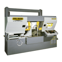
Front view dimensions of the S22A Production Saw.

Right Side Elevation Views

Right side view dimensions of the S22A Production Saw.

S22A General Views and Foundation Plan

General Plan View Details

Top view of the machine with operational dimensions.

Foundation Plan and Anchor Points

Dimensions for machine foundation and anchor points.

S-23A Bandsaw Specifications

S23 Cutting Capacity Diagram

S23A Production Saw Dimensions

Front Elevation Views

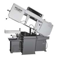
Front view dimensions of the S23A Production Saw.

Right Side Elevation Views

Right side view dimensions of the S23A Production Saw.

S23A General Views and Foundation Plan

General Plan View Details

Top view of the S23A with operational dimensions.

Foundation Plan and Anchor Points

Foundation and anchor point dimensions for S23A.

SECTION 9 - WARRANTY

Warranty Terms and Conditions

Terms and conditions of the manufacturer's warranty for the bandsaw.

PLC and Sequencer Parameters

Related product manuals