EasyManua.ls Logo

Hydreon RG-11 User Manual

Hydreon RG-11
7 pages
To Next Page IconTo Next Page
Page #1 background imageLoading...
Page #1 background image
LENS
O-RING
STRETCH BEFORE
INSTALLING
SHADE
NOTCHES IN RING
MATE WITH
RIBS IN LENS
PRINTED-CIRCUIT
BOARD (PCB)
SCREWS
(4 OF #6 X 1”)
HOUSING
19.16
.75
10.40
.41
6.40
.25
19.05
.75
9.53
.38
70.71
2.78
120.23
4.73
55.20
2.17
OPTICAL RAIN GAUGE
MODEL RG-11
INSTALLING THE RAIN SENSOR
1. Determine the Mode / Set DIP switches
You must set the DIP switches so that the RG-11
behaves the right way for your application. The pages
that follow describe each of the possible modes, and
how to set the DIP switches.
2. Mount the Rain Gauge
Mount the rain Gauge where it gets a clear
measurement of precipitation– away from overhangs,
etc.
The mounting arm is designed to fit over a strap 0.75”
(19 mm) wide. Two 0.25” (holes 6.35 mm) are placed
0.75” (19 mm) part.
The gland style connector goes in the bottom hole. Be
sure to use wire rated for outdoor (high-UV) use.
For conduit applications, the mounting arm may be
removed, and the wiring hole drilled out using a step drill
to accommodate a ½” EMT compression connector or
similar style of conduit connector.
3. Assemble the Rain Gauge as shown.
The silicone O-ring fits nicely in the lens groove, but it
can fall or slip out during assembly. After the unit is
assembled, verify that the O-ring is properly seated by
confirming that you can see it through the lens, all the
way around.
The Rain Gauge must be assembled when dry. Any
water trapped inside can condense and cause corrosion.
You may optionally add extra desiccant packets (not
supplied). If the Rain Gauge is not subject to splashing
or sprayed water, you may optionally vent the enclosure
MOUNTING ARM
CUT OFF FOR
CONDUIT-MOUNT
LED ON BOARD
ON when OUT
is active
EXPLODED VIEW
- APPLICATION WARNING -
Do not use the RG-11 in any application where the false
indication of water or a missed valid detection of water
could cause damage to life or property. It is the
responsibility of the system designer / integrator to
design redundancy into the system so that the failure of
any one component, including the RG-11 or other
sensor, does not result in disaster. The manufacturer of
the RG-11, Hydreon Corporation, will in no way be
liable for consequential damages due to the failure or
false indication of one of its sensors.
!
!
DIMENSIONAL VIEW

Other manuals for Hydreon RG-11

Question and Answer IconNeed help?

Do you have a question about the Hydreon RG-11 and is the answer not in the manual?

Hydreon RG-11 Specifications

General IconGeneral
BrandHydreon
ModelRG-11
CategoryAccessories
LanguageEnglish

Summary

Installing the Rain Sensor

Determine Mode and Set DIP Switches

Setting DIP switches for correct application behavior and modes.

Mount the Rain Gauge

Guidance on selecting a clear measurement location away from overhangs.

Assemble the Rain Gauge

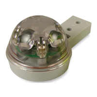
Instructions for proper assembly, ensuring the O-ring is seated correctly.

Rain Gauge Connections

Equivalent Schematic

Provides a schematic representation of the rain gauge connections.

Rain Gauge Wiring Examples

Line Voltage Control 'It's Raining' Application

Wiring example for line voltage control in 'It's Raining' mode.

Low Voltage 'It's Raining' Application

Wiring example for low voltage control in 'It's Raining' mode.

Tipping Bucket Replacement Example

Wiring example for replacing a tipping bucket sensor.

RG-11 Specifications

Electrical and Environmental Parameters

Covers input voltage, current drain, output specs, and operating temperature.

Feature Descriptions

Explains DIP switches, software revision, OUT LED, condensation, heater, and dark sensing.

J2 Connector and Communications

J2 Pin Assignments

Lists the pin functions for the J2 connector.

Remote Switching

Describes using J2 for remote switch operation.

RS-232 Communications

Information on enabling RS-232 communication with the device.

Mode 0: Tipping Bucket

Tipping Bucket Emulation Settings

Configuration options for emulating different tipping bucket sizes.

Mode 1: It's Raining

Rainfall Intensity Settings

Adjusting sensitivity levels for detecting rainfall intensity.

Monostable Extend Function

Extends output ON time for 15 minutes after rain stops.

Dark Detect Feature

Enables output activation based on low ambient light.

Mode 2: Condensation Sensor

Condensation Detection Settings

Configuring sensitivity for detecting condensation or frost.

Mode 3: Wiper Control

Wiper Speed and Cycle Control

Settings for controlling wiper speed and actuation cycle time.

External Relay Requirement

Emphasizes the need for an external relay for wiper motor control.

Mode 4: Irrigation Control

Irrigation Inhibit Settings

Options to inhibit watering based on rainfall or storm conditions.

Evaporation Rate Settings

Adjusting control based on normal or high evaporation rates.

Mode 6: Drop Detector

Drop Detection Thresholds

Settings for normal, sensitive, or high drop detection thresholds.

Drop Pulse Output

Configuring single or multiple pulses per detected drop.

Mode 7: First Flush / Rain Water Harvest

First Flush Level and Clean Time

Setting water accumulation thresholds and system clean time.

Gets Dirty Fast Setting

Enables faster system reset and halves clean time.

Safety, Liability, and Warranty

Liability Limitations

Hydreon's warranty covers only sensor cost, not consequential damages.

System Integrator Responsibility

Emphasizes integrator's role in ensuring safe installation and redundancy.

Case and Cosmetic Policy

Details warranty coverage for cosmetic issues like yellowing or minor cracks.