INTERMEDIATE SECTIONS - ZWISCHENSEKTIONEN
48
HCD3M-04
HC-D3M
40
Sectional Valve - WEGEVENTIL IN SEKTIONSBAUWEISE
1
2
3
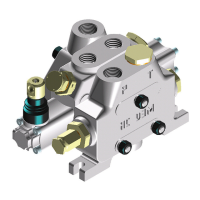
Direct acting
pressure relief
valve
Direktbetätigtes
Druckbegren-
zungsventil
TYPE DESIGN DIAGRAM DESCRIPTION
TYP ZEICHNUNG SCHEMA BESCHREIBUNG
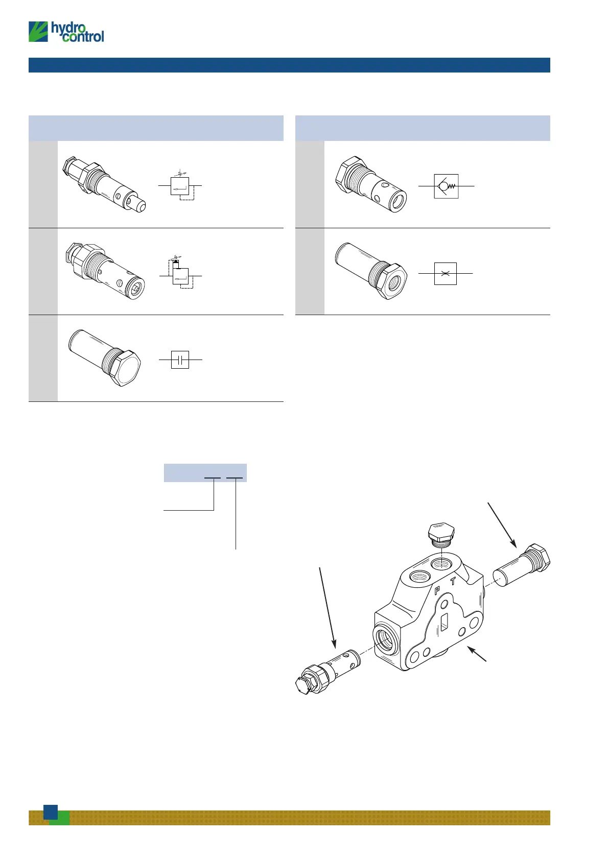
Komponenten für die SektionValves identification
Ventilzusammenstellung
Zwischeneingangssektion
Valve arrangement on inlet
intermediate section
A
B
INLET SIDE
EINGANGSSEITE
Example - Beispiel: 009 = 2A-3B
Pressure relief valve in port A side
Druckbegrenzungsventil in Anschluss A
Plug replaces pressure relief valve in port B side
Stopfen anstelle Druckbegrenzungsventil an Anschluss B
The code identifies: with a number, the type of valve; with a
letter, its position on the inlet section.
(A) = spool action side
(B) = spool return action side
Die Bestellbezeichnung gibt an: mit einer Zahl die
Ventilausführung und mit einem Buchstaben seine Position
in der Eingangssektion.
(A) = Seite der Kolbenbetätigung
(B) = Seite der Kolbenrückführung
 Loading...