INTERMEDIATE SECTIONS - ZWISCHENSEKTIONEN
48
HCD3M-04
HC-D3M
41
Sectional Valve - WEGEVENTIL IN SEKTIONSBAUWEISE
001 002 008 009 010 016 017 018 019 020 027 028 029 030
1A-3B 1A-4B 1A-11B 2A-3B 2A-4B 2A-11B 3A-1B 3A-2B 3A-3B 3A-4B 3A-11B 4A-1B 4A-2B 4A-3B
037 084 085 086 087
4A-11B 11A-1B 11A-2B 11A-3B 11A-4B
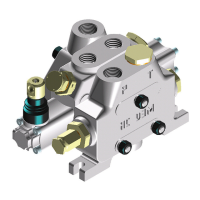
Eingangsposition und bGewindeausführung
Inlet position and available thread type
Upper inlet
Eingang oben
A
M01 G04 U03
U04
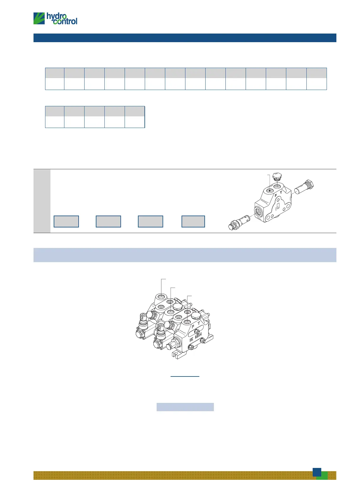
Ventilkombination
Valves combination
Complete configuration samples for HC-D3M with intermediate inlet section (BE)
Vollständiges Konfigurationsbeispiel für ein HC-D3M Wegeventil mit Zwischeneingangssektion (BE)
Right inlet section .......................................IR 001 150 A G04 .............................Rechte Eingangssektion
Working section .................................W001A H001 F001A RP GO4..............................Wegeventilsektion
Intermediate inlet section ...........................BE 009 120 A G04 ..........................Zwischeneingangssektion
Working section .................................W001A H001 F001A RP GO4..............................Wegeventilsektion
Outlet section....................................................TJ A GO4...............................................Ausgangssektion
HC-D3M/2
 Loading...