7
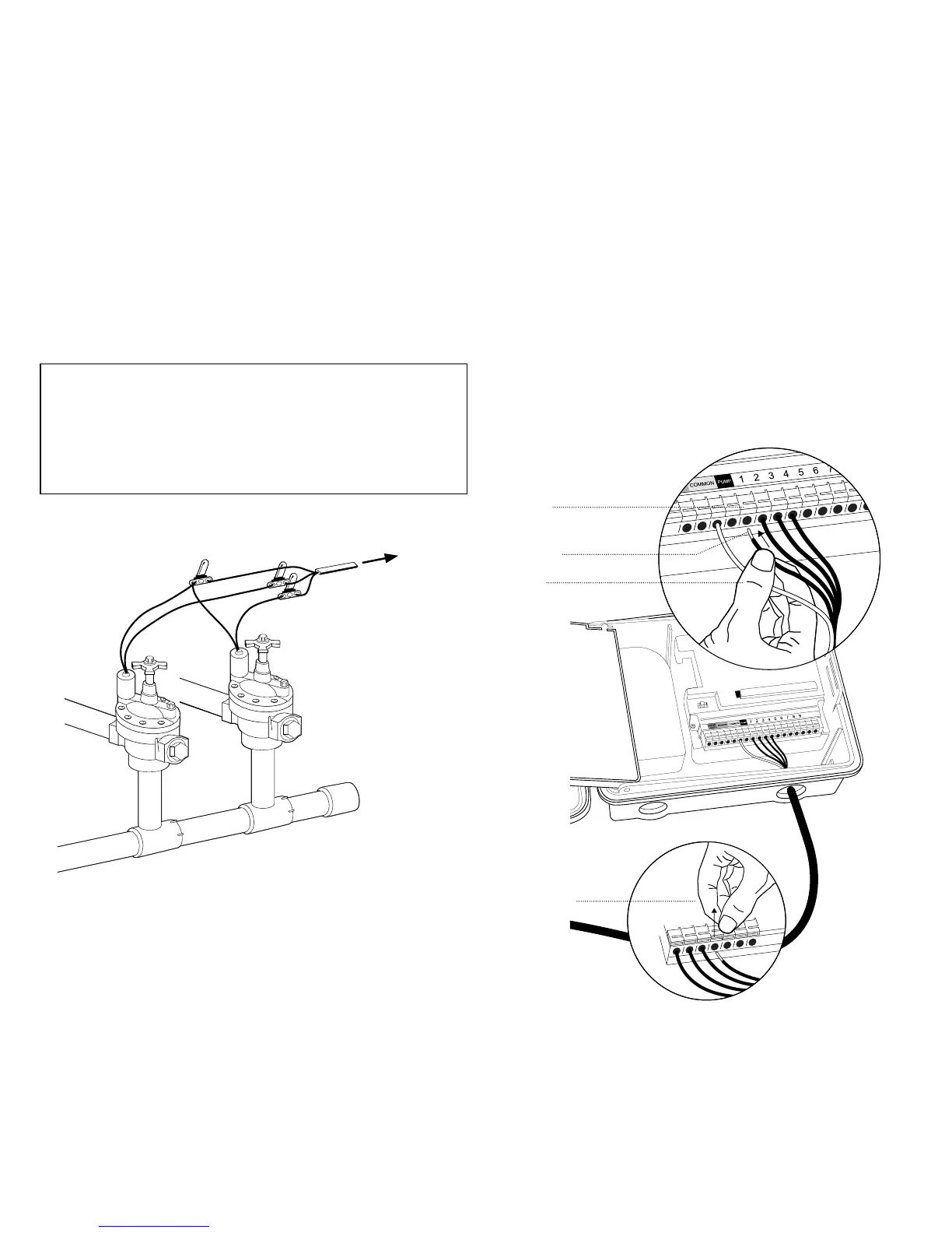
3. Connect Valve Wires to Controller
• Strip 12 mm of the plastic insulation off the end of each
valve wire at the controller.
• Connect one wire from each valve (it doesn’t matter
which wire) to a single “Common” sprinkler wire
(usually white).
• Connect the remaining wire from each valve to a
separate colored sprinkler wire. See Figure 3
Note: The maximum loading for each station/pump is 250mA,
the maximum loading for the controller is 500mA.
If the distance between the sprinkler controller and valves is under
210 m, use sprinkler wire or .5mm (20 gauge AWG) plastic jacketed
thermostat wire to connect the sprinkler controller to the valves. If
the distance is over 210 m, use 1.5mm (16 gauge AWG) wire.
Important: All wires should be joined together using good quality
waterproof cable connectors.
Wiring Electric Valves
Each valve has two wires. One wire (it doesn’t matter which
one) is to be connected as the common.
The other valve wire is to be connected to the specific station
wire that will control that valve. The common wires for all the
valves can be connected together to one common wire going
Station 1
Push tab
upward to
release wire
Strip wire
Push in
Only connect one valve to
each terminal (station).
Figure 4
To
Timer
Wire Nut
Solenoid
Common Wire
Valve
Figure 3:
Wiring Electric Valves
to the controller. To avoid electrical hazards, only one valve
should be connected to each station. See Figure 4
Important: The wire can be buried in the ground; however, for
more protection wires can be pulled through PVC pipe and buried
underground. Be careful to avoid burying the wires in locations
where they could be damaged by digging or trenching in the future.
Your controller is equipped with the simple “push-in” terminals
for easy connection. Connect common wire to the common
terminal. Connect remaining wires to corresponding terminal
locations.
 Loading...