Step 1 Unplug the sump pump from the back of the “piggy- back plug”.
Step 2
Unplug the “piggyback plug” from the 120 VAC and set aside. The HC6000v2 completely
replaces this component.
Step 3
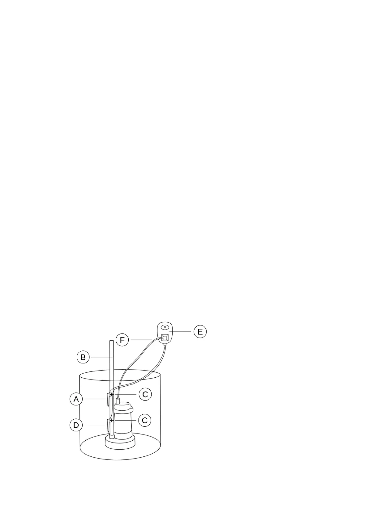
Secure the red sensor (A) to the discharge pipe (B) with tie wrap (C) where the pump is
intended to turn on.
NOTE: Recommended height for the Red Sensor is slightly below the Drain Tile (Water Inlet
Pipe).
Step 4
Secure the black sensor (D) to the discharge pipe
(B) with tie wrap (C) where the pump is intended to turn off.
Step 5
Check that the red sensor (A) is positioned above
the black sensor (D).
Step 6
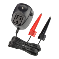
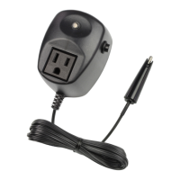
Plug the control module (E) into a 3-prong 120 VAC outlet.
NOTE: The output will turn on briefly and the LED will illuminate red. If the Red Sensor
detects water, a pump cycle will begin.
Step 7
Plug the sump pump power cord (F) into the con- trol module (E).
NOTE: The HC6000v2’s output is rated for a maxi- mum of 1 HP and/or 15 amps at 120
VAC.
Step 8
TEST YOUR INSTALLATION BEFORE LEAVING IT FOR UNATTENDED USE.
NOTE: This product will not work if tested in a cup of water. See How the Sensor Works:
Do I need a ground wire? On Page 2 for more information.
Installation Key
A. Red Sensor (Hi-Sensor)
B. Discharge Pipe
C. Tie Wrap