2
Thank you for purchasing your
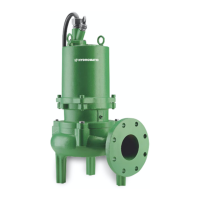
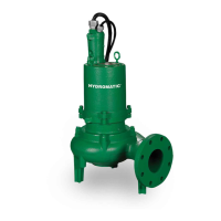
Hydromatic
®
pump. To help ensure
years of trouble-free operation,
please read the following manual
carefully.
Before Operation:
Read the following in structions
care ful ly. Reasonable care
and safe meth ods should be
practiced. Check local codes and
requirements before installation.
Attention:
This manual contains important
information for the safe use of
this product. Read this manual
completely before using this
product and refer to it often
for con tin ued safe product use.
DO NOT THROW AWAY OR
LOSE THIS MAN U AL. Keep
it in a safe place so that you may
refer to it often.
Unpacking Pump:
Remove pump from carton.
When un pack ing unit, check for
con cealed damage. Claims for
damage must be made at the
receiving end through the delivery
carrier. Dam age cannot be
processed from the factory.
WARNING: Before handling
these pumps and controls,
always disconnect the power
first. Do not smoke or use
sparkable electrical devices or
flames in a septic (gaseous) or
possible septic sump.
Pumps Not Operating or
in Storage:
Pumps with carbon ceramic seals
must have impellers manually
rotated (6 rev o lu tions) after
setting non-op er a tion al for 3
months or longer and prior to
electrical start-up.
Pump:
This series of submersible pumps
is sup plied for 1 and 3 phase
and for 200, 230, 460 or 575
volts. Power ca ble is supplied
with a green wire for ground.
Be sure green wire is connected
to a ground lug in the control
panel, and the control panel must
be connected to a ground rod or
ground wire from supply service.
NOTE: All single phase pumps
require properly sized start
capacitor, start relay and run
capacitor in the panel.
Sump Level Control:
Sump level is controlled by
Hydromatic 3900 mercury
switch level controls. The 3900
level controls is a metal case
mercury switch sealed in a solid
polyurethane float. The float
is held in position by a weight
at tached to the power cord above
the float. The cord supports the
float and is adjusted for height
from the sur face.
Typical duplex systems use three
floats; the lowest float turns the
pumps off, the next higher float
starts the lead pump, the next
higher float (override) starts the
lag pump. The pumps alternate
on successive cycles.
Two pumps operate together only
if sump level rises to the third or
over ride float. The override float
also brings on the sec ond pump in
General
Information
case of failure of the first pump.
Extra floats with ap pro pri ate
con trols can be sup plied for alarm
functions. Triplex sys tems use
four floats. The fourth highest
float brings on the second lag
pump. Three pumps operate
together only if sump level rises to
the fourth float (sec ond override).
This float also brings on the third
pump in case of fail ure of either or
both of the first two pumps.
Alarm Controls:
The alarm float is usually set
above the override level so the
alarm will sig nal only if the
override level is ex ceed ed.
How ev er, some engineers pre fer
to have the alarm float set be low
the override lev el as it is pos si ble
for one pump to fail and the other
pump to operate on the over ride
level with the sump level never
reach ing the alarm level. This is
par tic u lar ly true in cases of low
inflow capacity.
Electrical Control Panel:
It is recommended that the
Hydromatic con trol panel be used
with all pumps as proper start
com po nents and pump protection
are fur nished.
NOTE: All single phase pumps
require properly sized start
capacitor, start relay, and run
capacitor in the control panel.
IMPORTANT: If Hydromatic
control panel is not used and
the motor fails be cause of
im proper components, the
warranty is void.
Hydromatic electrical equipment
is installed in a weatherproof
en clo sure. Electrical equipment
in cludes a main cir cuit breaker
 Loading...