3
Part No. Description
48-101 HydroStat Remote Mount Kit with 24" sensor
48-102 HydroStat Remote Mount Kit with 48" sensor
48-103 HydroStat Remote Mount Kit with 10' sensor
48-104 HydroStat Remote Mount Kit with 20' sensor
48-121 HydroStat Pipe Mounting Kit with 48" sensor
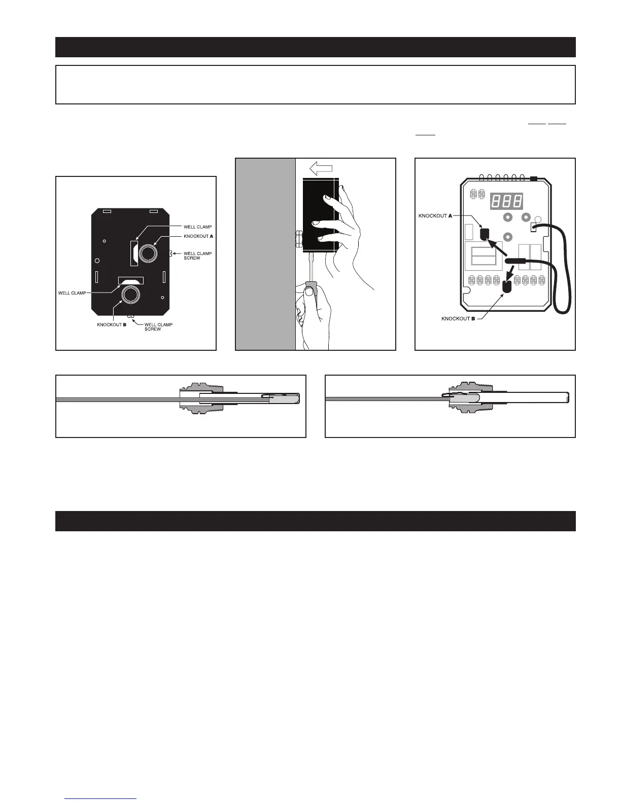
MOUNTING THE CONTROL
STEP 1
Two mounting positions
are available on the back of the control
(Fig. 1). Select which of the two positions
(2 knockouts) is best for the location of
the control. Remove the knockout.
STEP 2 Place control on the well.
While holding box against well nut,
tighten well clamp screw. (Fig. 2)
BACK OF
FUEL SMART HYDROSTAT BOX
FIG. 1 FIG. 3FIG. 2
NOTE: In the case of space restrictions, the Fuel Smart HydroStat control may be mounted in a horizontal orientation without any
loss of function. Hydrolevel recommends vertical mounting, when possible, for proper orientation of LED display.
STEP 3 Insert sensor ALL THE
WAY into well through the knockout (A
or B) you have chosen. (Fig. 3)
IMPORTANT Make sure that the immersion well or Electro-Well™ is installed in the boiler manufacturer’s designated
temperature limit control tapping.
NOTE:
If installing an Electro-Well, pipe sealing compound should be used. Teflon tape is not recommended.
IMPORTANT – Sensor must be inserted all the way into the well for proper operation.
CORRECT INCORRECT
REMOTE MOUNTING KITS
Remote Mounting Kits are available separately for mounting the Fuel Smart HydroStat control box in a remote location. Each kit
includes mounting hardware and a remote sensor.
HydroStat 3200-Plus Instructions_ HydroStat Instructions.8pg 12/1/17 10:43 AM Page 3