HyperFlight.co.uk Blaster 2 Assembly Guide
Rudder & AMT Controls Snakes
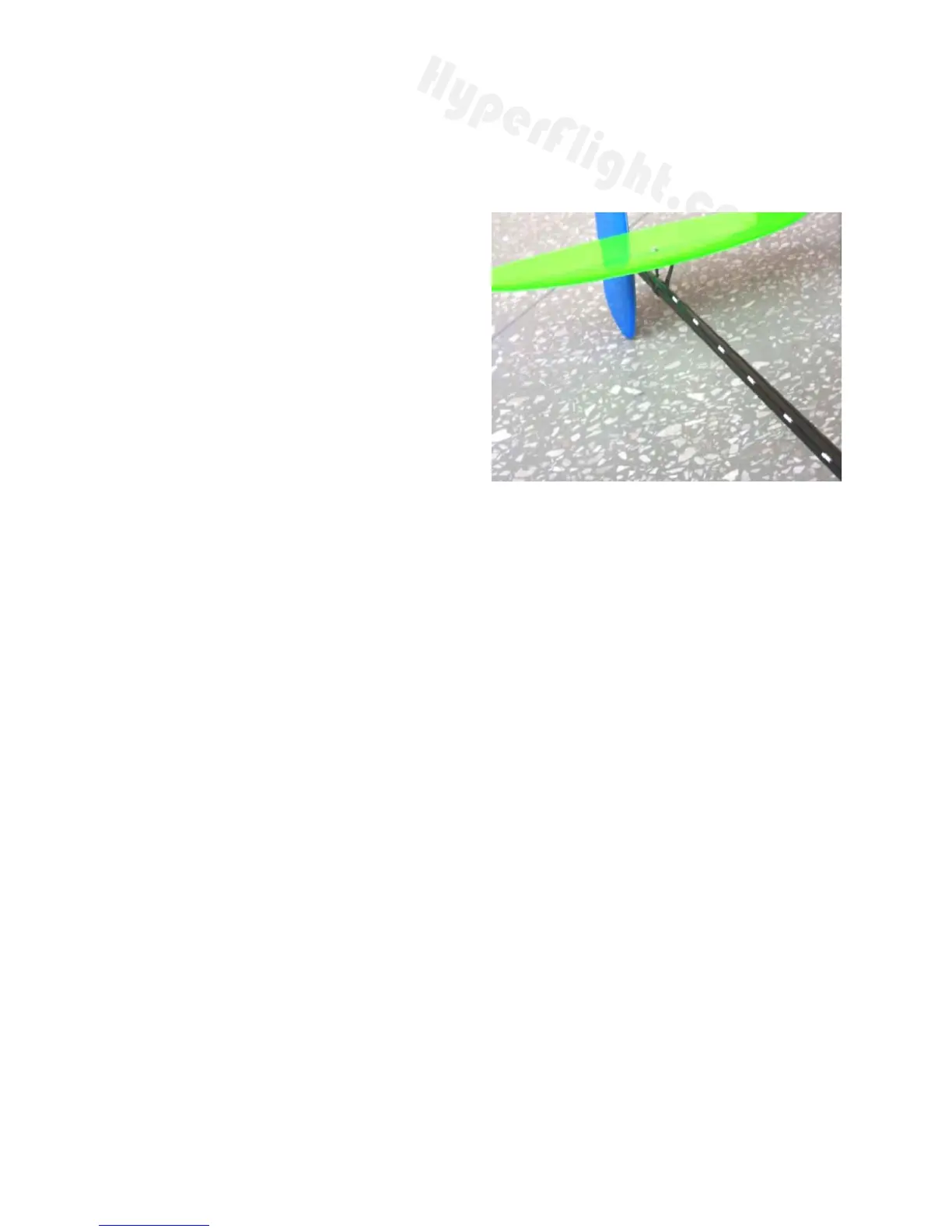
The current preferred method of guiding the pushrods, is to keep the pushrods outside
the boom and use 10mm long tubes (cut from the white outer tube supplied) to guide
the 0.8mm carbon rod pushrod to the rear.
This is lighter, easier to construct, and
easier to maintain than internal pushrods.
The extra drag (if any) is more than offset by
the weight reduction. Cut the white tube into
10mm lengths and place it on the carbon
pushrod (or some piano wire if available,
any slips with CA will be less problematic).
Then route the pushrod along the boom to
the rudder horn and towards the AMT V-
mount. Use the smallest drops of thick CA to
attach the guide tubes to the boom every
approx 5cm. Don't use thin CA, and don't
use too much as the CA can easily wick into
the guide tube and seize the pushrod.
(Original method, not recommended) If internal pushrods are preferred please buy
some of our 1.4mm PTFE tube (as the white pushrod outers supplied by Vladimir's
Models are too short to allow internal pushrods) and proceed as follows. Wrap a layer
of masking tape around the boom to cover an area approximately 70mm in front of the
front edge of the AMT V-mount. Mark a spot 55mm in front of the V-mount, exactly on
top of the boom in alignment with the AMT control horn. Similarly place some masking
tape around the boom immediately behind the front RIGHT HAND side of the fin and
mark a spot on the boom about 3mm back from the front of the fin and at a position on
the boom exactly 90 degrees to the fin. CAREFULLY drill a 2.5mm hole at both
positions. Remove the masking tape, and then elongate each hole so that the outer
tubes for the carbon control rods exit the boom at right angles to, and in direct
alignment with their respective control horns on the AMT V-mount and the rudder horn,
which is still to be fitted.When satisfied with the fit of the push rod tubes, fit them in
position, leaving short lengths of both tubes protruding from the boom. When passing
the tubes down the inside of the boom, MAKE SURE that they exit in the correct place
in the nose of the model to fit in with your proposed servo installation. Carefully secure
the tubes in position with a cyano and then carve off the excess with a scalpel blade to
leave them flush with the surface of the tail boom.
Place a piece of masking tape on the rudder in line with the centre of the tail boom and
mark the position of the rudder control horn. Carefully cut a slot in the rudder at the
position marked with a sharp scalpel blade, then remove the masking tape and fix the
rudder horn in place using a very small amount of epoxy adhesive or cyano. The next
step is to fit two of the four small steel push rod ends supplied to the carbon push rods.
This can be done using cyano, in which case it must be done quickly to ensure that the
carbon push rods fit right into the push rod ends before the cyano sets. Before
installing the push rods into their tubes, (from the rear of the boom), make 90 degree
bends in the thin solid section of the push rod ends ready to fit into their respective
control horns.
(c) 2009 HyperFlight.co.uk, Drybank Farm, Ettington, Stratford upon Avon, Warks, CV37 7PD.
5
 Loading...