13 Installation Mains and CT Connection
Step 6 (At the Consumer Unit)
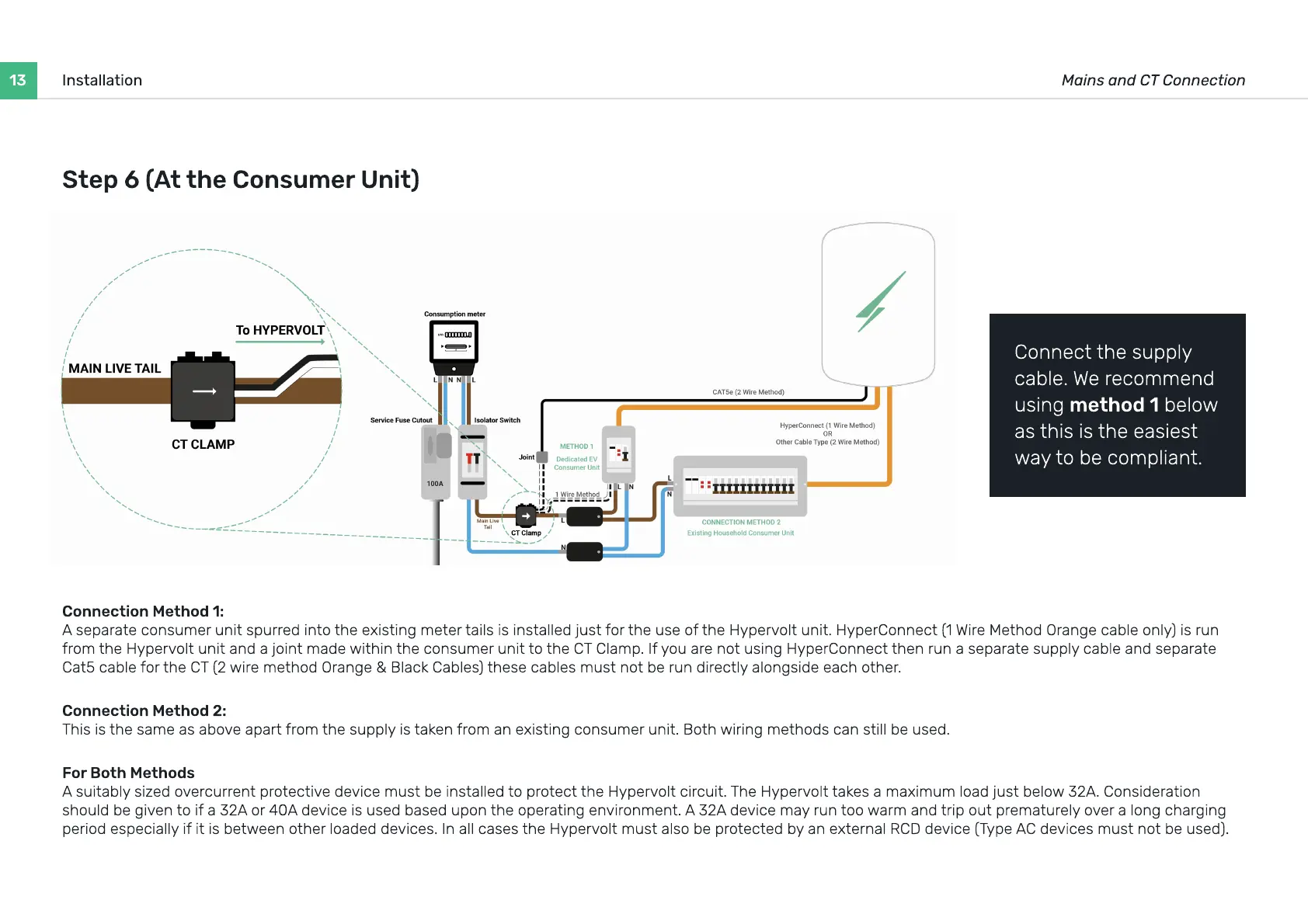
Connection Method 1
A separate consumer unit spurred into the existing meter tails is installed just for the use of the Hypervolt unit. HyperConnect (1 Wire Method Orange cable only) is run
from the Hypervolt unit and a joint made within the consumer unit to the CT Clamp. If you are not using HyperConnect then run a separate supply cable and separate
Cat5 cable for the CT (2 wire method Orange & Black Cables) these cables must not be run directly alongside each other.
Connection Method 2
This is the same as above apart from the supply is taken from an existing consumer unit. Both wiring methods can still be used.
For Both Method
A suitably sized overcurrent protective device must be installed to protect the Hypervolt circuit. The Hypervolt takes a maximum load just below 32A. Consideration
should be given to if a 32A or 40A device is used based upon the operating environment. A 32A device may run too warm and trip out prematurely over a long charging
period especially if it is between other loaded devices. In all cases the Hypervolt must also be protected by an external RCD device (Type AC devices must not be used).
Connect the supply
cable. We recommend
using method 1 below
as this is the easiest
way to be compliant.
 Loading...