This document is a service and repair manual for Hyster B214 series forklifts, specifically covering models H400HD-EC, H440HDS-EC, H450HD-EC, H450HDS-EC, and H500HD-EC. It also references other Hyster models that utilize the same transmission types, including H16.00-18.00XM/XMS-12 (H400-450HD/HDS) [A236], H16.00-22.00XM-12EC (H400-500HD/HDS-EC) [B214], H16XM-12, H18XM-12, H20XM-12, H22XM-12 (H400HD, H450HD, H500HD, H550HD) [B236], H16XM-12EC, H18XM-12EC, and H22XM-12EC (H400HD-EC, H450HD-EC, H500HD-EC) [C214]. The primary focus of this specific section of the manual is the transmission repair for TE13 and TE17 transmissions.
Function Description:
The Hyster B214 series forklifts are heavy-duty material handling machines designed for lifting and transporting heavy loads. The manual specifically addresses the transmission system, which is a critical component responsible for transferring power from the engine to the drive wheels, enabling the forklift to move and operate at various speeds and directions. The TE13 and TE17 transmissions are integral to the forklift's propulsion and operational efficiency. The TE13 transmission is designed for trucks with a 142 kW engine option, while the TE17 transmission is used with the 164 kW engine option, indicating different power output capabilities and potentially different load capacities or performance characteristics for the forklifts they are installed in. The transmission includes various internal components such as clutch drums (1st, 2nd, 3rd, Forward, Reverse), turbine shaft, output shaft, gears, bearings, and a control valve, all working in concert to manage power delivery.
Important Technical Specifications (as inferred from the manual):
- Transmission Models Covered: TE13 and TE17.
- Engine Compatibility: TE13 for 142 kW engines; TE17 for 164 kW engines.
- Forklift Series: Hyster B214 (H400HD-EC, H440HDS-EC, H450HD-EC, H450HDS-EC, H500HD-EC).
- Related Models: H16.00-18.00XM/XMS-12 (H400-450HD/HDS) [A236], H16.00-22.00XM-12EC (H400-500HD/HDS-EC) [B214], H16XM-12, H18XM-12, H20XM-12, H22XM-12 (H400HD, H450HD, H500HD, H550HD) [B236], H16XM-12EC, H18XM-12EC, H22XM-12EC (H400HD-EC, H450HD-EC, H500HD-EC) [C214].
- Weight Consideration: The transmission is heavy, requiring a lifting device with a minimum capacity of 1000 kg (2205 lb) for removal.
- Special Tool Dimensions: A special tool for the FWD/3RD shaft assembly has specific dimensions: Ø52.50 mm (2.07 in) diameter, 90 mm (3.54 in) height, and 470.46 mm (18.52 in) overall length.
- Electrical System Diagrams: Referenced in Diagrams 8000 SRM 1312 for A236 and Diagrams 8000 SRM 1281 for B214, indicating integrated electrical controls for the transmission.
- Fuel Types: The manual mentions gasoline, Liquid Petroleum Gas (LPG), Compressed Natural Gas (CNG), and Diesel fuel, implying that these forklifts can be powered by various internal combustion engines.
Usage Features (as implied by maintenance procedures):
The forklifts are designed for robust operation, requiring regular maintenance and careful handling during service. The transmission is a complex assembly, suggesting that the forklifts are intended for demanding applications where reliable power delivery is crucial. The presence of multiple clutch drums (1st, 2nd, 3rd, Forward, Reverse) indicates a multi-speed transmission, allowing for varied operational speeds and directional control (forward/reverse). The inclusion of a torque converter suggests smooth power transfer and adaptation to varying load conditions. The use of sensors (engine speed, temperature, drum speed) implies a degree of electronic control and monitoring for optimal performance and fault detection.
Maintenance Features:
The manual provides detailed, step-by-step instructions for the removal, disassembly, cleaning, inspection, and assembly of the transmission components. This comprehensive approach ensures that technicians can perform thorough repairs.
- Safety Precautions: Emphasizes critical safety measures such as disconnecting battery connectors, using proper lifting mechanisms, wearing safety glasses, blocking the unit, keeping the work area clean, using correct and clean tools, and always using HYSTER APPROVED parts. It also highlights precautions for handling flammable fuels and batteries.
- Structured Repair Process: The repair process is broken down into logical sections: General, Transmission Repair (Remove, Disassemble, Clean and Inspect, Assemble, Install), Control Valve Removal and Installation, and Torque Specifications.
- Component-Specific Disassembly/Assembly: Detailed steps are provided for individual components like the transmission case, clutch drums, shafts, converter housing, charging pump, and control valve.
- Special Tools: The manual specifies the use of special tools, such as bearing pullers and custom lifting tools, for certain procedures, indicating the precision required for maintenance.
- Identification and Labeling: Instructions advise putting identification tags on wires to ensure correct reconnection, which is crucial for complex electrical systems.
- Fluid Management: Procedures include draining transmission oil and handling oil lines, emphasizing proper fluid management during service.
- Torque Specifications: A dedicated section for torque specifications for lubricated or plated screw threads is included, ensuring components are fastened correctly to prevent damage or failure.
- Warning and Caution System: The manual uses distinct WARNING (orange background, potential for death or serious injury) and CAUTION (yellow background, potential for minor injury or property damage) symbols and words to alert technicians to potential hazards.
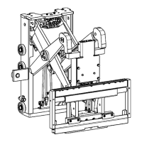
- Visual Aids: The manual is heavily illustrated with images for each step of the disassembly process, making it easier for technicians to follow instructions and identify components. For example, Figure 1 shows the front view of the TE17 transmission, and subsequent figures illustrate specific removal steps like drive plate removal, filter element removal, and component lifting.
- Diagnostic Information: While this section focuses on repair, the "General" section mentions "diagnostics of the TE-13 and TE-17 transmission," suggesting that the full manual likely includes diagnostic procedures to identify issues before repair.