2000 SRM 1233 General
General
This section has the description and operation of
the hydraulic components that are assembled on the
Hydraulic Plate. The section also has disassembly,
assembly, repair, calibration, and troubleshooting
for most components that are assembled on the
Hydraulic Plate.
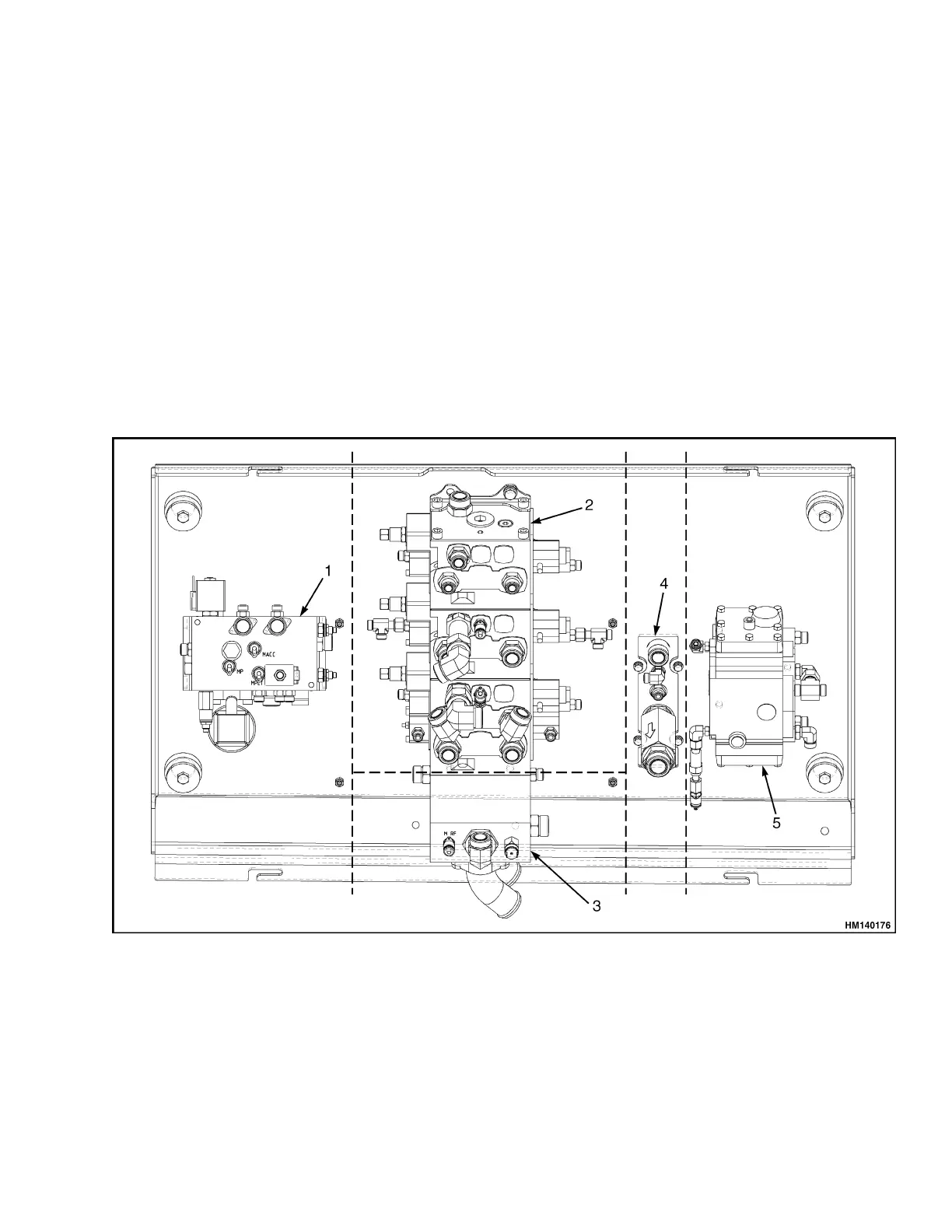
The five sections of the Hydraulic Plate are as follows
(see Figure 1):
• Section 1 contains the manifold with most of the
hydraulic system valves and test ports.
• Section 2 contains the main control valve.
• Section 3 contains the return manifold.
• Section 4 contains brake manifold.
• Section 5 contains the flow amplifier.
The Hydraulic Plate is an integral part of the total
hydraulic system. See the following sections for de-
scription, operation, and repair information of hy-
draulic components in these systems:
• Hydraulic System 1900 SRM 1239
• Steering System 1600 SRM 1109
• Parking Brake 1800 SRM 1117
• Service Brake 1800 SRM 1038
•Mast4000 SRM 1160
• Hydraulic Gear Pumps 1900 SRM 97
• Tilt Cylinders 2100 SRM 1116
• Extendable Container Attachment (Elme),
812, 813, 815, and 818 Series 5000 SRM 723
(F117 only)
1. MANIF
OLD SECTION
2. MAIN CONTROL VALVE SECTION
3. RETURN MANIFOLD SECTION
4. BRAKE
MANIFOLD SECTION
5. FLOW AMPLIFIER SECTION
Figure 1. Hydraulic Plate Sections
1
 Loading...