2000 SRM 1025 Control Valve
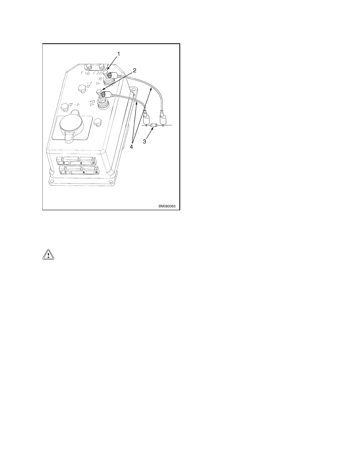
Figure 1. Discharging the Capacitor
Legend for Figure 1
1. NEGATIVE CONNE
CTION
2. POSITIVE CONNECTION
3. 200-OHM, 2-WATT RESISTOR
4. INSULATED JUMPE
RWIRES
Control Valve
CAUTION
The hydraulic oil must be kept clean to prevent
damage to the control valve.
The control valve is part of the lift pump and mo-
tor assembly and is replaceable but not adjustable.
When the operator selects a hydraulic function by
pressing a button on the control handle, a signal is
sent to the traction/lift controller, is processed, and
is sent to the pump assembly. Lifting speed is con-
trolled by varying the pump motor speed. Lower-
ing speed is controlled by a proportional electro-hy-
draulic valve on the pump assembly.
The control valve is designed with close tolerances
and must be kept clean to work properly.
3
 Loading...