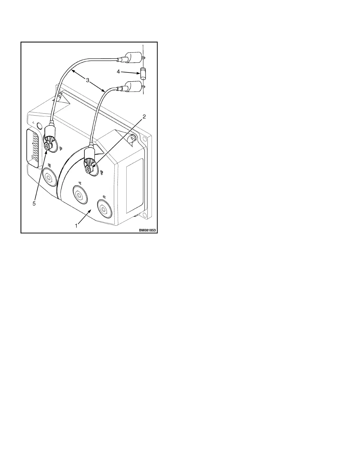
Figure 1. Discharging the Capacitors
Legend for Figure 1
1. CONTROLLER
2. POSITIVE CONNECTION
3. INSULATED JUMPER WIRES
4. 100-OHM, 25-WATT RESISTOR
5. NEGATIVE CONNECTION
Description
AC MOTOR CONTROLLER
The controller is a solid-state, AC motor controller.
It can control the traction motor, brake, and hy-
draulic system. The controller receives inputs from
the control handle by serial communication, and di-
rect inputs from other switches depending on
model. These may include the following:
• Key switch
• Control handle arm position switch
The controller directly controls the traction motor,
lift pump motor, main contactor, and the brake.
The motor controller controls the speed of the trac-
tion motor and the hydraulic lift pump motor oper-
ation. The controller software provides self diagnos-
tics which are accessed by means of a Curtis hand-
set.
PRINCIPLES OF OPERATION
The Traction Motor Controller uses a sophisticated
microprocessor to control the logic and operation of
the controller, eliminating the need for forward and
reverse contactors. The controller has many pro-
grammable features, including maximum speed, ac-
celeration rate, neutral braking, and braking cur-
rent limit. The controller includes a full range of
features as well as diagnostic and setup capability
for reliable operation.
NOTE: There are no user-serviceable parts in the
Curtis controller. No attempt should be made to
open, repair, or otherwise modify the controller. Do-
ing so may damage the controller and will void the
warranty.
Description 2200 SRM 1507
2
 Loading...