INSTALL
1.
Make certain the mounting surface for the trac-
tion motor controller is clean. There should be
no dirt between the contactor panel mounting
plate and the traction motor controller.
2.
Connect wires and cables to controller termi-
nals. See Figure 2.
3.
Refer to Programming Controller for setup of
the controller.
The motor controller controls the speed of the trac-
tion motor and the hydraulic pump motor opera-
tion. The complete unit must be replaced if correct
troubleshooting methods show that the unit is dam-
aged.
PROGRAMMING CONTROLLER
The controller can be programmed using a 1311
handset. The areas that can be programmed are lis-
ted in Table 1 along with the adjustable ranges.
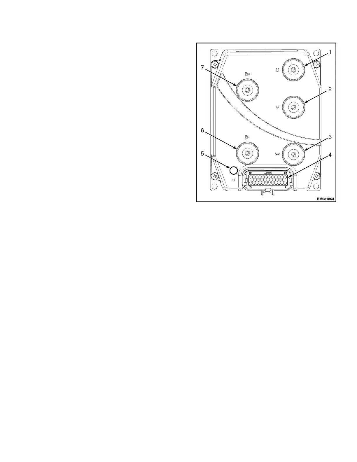
1. TRACTION MOTOR CONNECTION "U"
2. TRACTION MOTOR CONNECTION "V"
3. TRACTION MOTOR CONNECTION "W"
4. CONNECTOR
5. LED INDICATOR
6. B− CONNECTION
7. B+ CONNECTION
Figure 2. Controller
2200 SRM 1507 Description
3