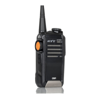
Circuit Description
1. Frequency Configuration
The receiver utilizes double conversion superheterodyne. The first IF is 49.95MHz and the
second is 450KHz. The first local oscillator signal is supplied by PLL circuit; and the
second (50.4MHz) is generated from the frequency tripling of TCXO (16.8MHz). The PLL
circuit generates the frequencies required for transmission. (See Fig.1).
Frequency Range:
136MHz—174MHz;
400MHz—470MHz;
450MHz—500MHz;
480MHz—530MHz;
350MHz—400MHz;
2.
2. 2.
2.
Receiver Circuit
The receiver section configuration is shown as Fig. 1.
Fig 1 Receiver Circuit
2.1 RF AMP BPF
It consists of BPF (LC resonant circuit where D107, D108 and D109 are located), RF
amplifier (Q111) and BPF (D110 and D111). The range of bandpass frequency is the
frequenc range of the radio itself. The signal is filtered by the BPF to eliminate unwanted
signals before going to the first mixer.
2.2 The First Mixer
The signal from BPF is mixed with the first local oscillator signal from PLL circuit at the first
mixer (Q112) to become a 49.95MHz first IF signal. The first IF signal is then fed through
crystal filter (XF200) to further remove spurious signals.
2.3 IF Amplifier
 Loading...