EasyManua.ls Logo

Hyundai 15L 7M User Manual

Hyundai 15L 7M
247 pages
To Next Page IconTo Next Page
Page #1 background imageLoading...
Page #1 background image
CONTENTS
SECTION 1 GENERAL
Group 1 Safety Hints
----------------------------------------------------------------------------------------------------
1-1
Group 2 Specifications
------------------------------------------------------------------------------------------------
1-5
Group 3 Periodic Replacement
-----------------------------------------------------------------------------------
1-13
SECTION 2 REMOVAL AND INSTALLATION OF UNIT
Group 1 Structure
--------------------------------------------------------------------------------------------------------
2-1
Group 2 Removal and Installation of Unit
--------------------------------------------------------------------
2-2
SECTION 3 POWER TRAIN SYSTEM
Group 1 Structure and Operation
--------------------------------------------------------------------------------
3-1
Group 2 Troubleshooting
---------------------------------------------------------------------------------------------
3-19
Group 3 Disassembly and Assembly
--------------------------------------------------------------------------
3-25
SECTION 4 BRAKE SYSTEM
Group 1 Structure and Function
----------------------------------------------------------------------------------
4-1
Group 2 Operational Checks and Troubleshooting
-----------------------------------------------------
4-8
Group 3 Tests and Adjustments
----------------------------------------------------------------------------------
4-10
SECTION 5 STEERING SYSTEM
Group 1 Structure and Function
----------------------------------------------------------------------------------
5-1
Group 2 Operational Checks and Troubleshooting
-----------------------------------------------------
5-10
Group 3 Disassembly and Assembly
--------------------------------------------------------------------------
5-12
SECTION 6 HYDRAULIC SYSTEM
Group 1 Structure and Function
----------------------------------------------------------------------------------
6-1
Group 2 Operational Checks and Troubleshooting
-----------------------------------------------------
6-22
Group 3 Disassembly and Assembly
--------------------------------------------------------------------------
6-26
SECTION 7 ELECTRICAL SYSTEM
Group 1 Component Location
-------------------------------------------------------------------------------------
7-1
Group 2 Electrical Circuit
---------------------------------------------------------------------------------------------
7-2
Group 3 Component Specification
------------------------------------------------------------------------------
7-9
Group 4 Connector Destination
-----------------------------------------------------------------------------------
7-10
Group 5 Troubleshooting
---------------------------------------------------------------------------------------------
7-12
Question and Answer IconNeed help?

Do you have a question about the Hyundai 15L 7M and is the answer not in the manual?

Hyundai 15L 7M Specifications

General IconGeneral
BrandHyundai
Model15L 7M
CategoryForklifts
LanguageEnglish

Summary

Foreword

Manual Structure Overview

Details the division of the service manual into sections for better understanding.

Purpose of the Service Manual

Explains the manual's aim to improve repair quality by providing understanding and correct procedures.

SECTION 1 GENERAL

Safety Hints

Provides essential safety guidelines for handling the machine and performing maintenance.

Specifications

Lists general and specific technical data for the machine's components and performance.

Periodic Replacement Schedule

Details the recommended intervals for replacing consumable parts for operational safety.

SECTION 2 REMOVAL AND INSTALLATION OF UNIT

Unit Structure Overview

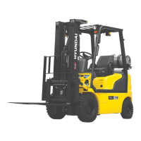
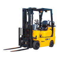
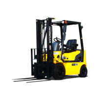
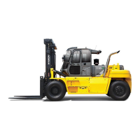
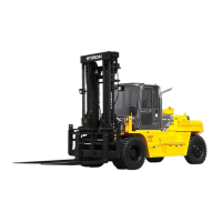
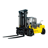
Identifies the main components and their locations within the unit.

Removal and Installation Procedures

Provides step-by-step instructions for disassembling and assembling unit components.

SECTION 3 POWER TRAIN SYSTEM

Power Train Diagram and Structure

Illustrates the overall power train layout and details the structure of key components.

Power Train Specifications

Lists technical specifications for the torque converter, transmission, axle, and wheels.

Torque Converter Details

Provides structural breakdown and hydraulic circuit information for the torque converter.

Transmission System

Details the structure, installation view, operation, and components of the transmission.

Drive Axle System

Explains the installation view, structure, operation, and assembly of the drive axle.

Power Train Troubleshooting

Lists common problems, probable causes, and remedies for the power train system.

Transmission Disassembly

Provides detailed steps for disassembling the transmission assembly and its components.

SECTION 4 BRAKE SYSTEM

Brake System Structure and Function

Describes the outline, specifications, and components of the foot and parking brake systems.

Brake Pedal and Piping Structure

Illustrates the brake pedal, parking lever, reservoir, and master cylinder layout.

Brake System Operational Checks

Details procedures for checking brake piping and parking brake operation.

Brake System Troubleshooting

Lists common brake problems, their causes, and recommended remedies.

Brake System Tests and Adjustments

Provides procedures for air bleeding and adjusting brake pedal height and play.

SECTION 5 STEERING SYSTEM

Steering System Structure and Function

Describes the overall steering system layout and its main components.

Hydraulic Circuit Operation

Illustrates the hydraulic circuit and explains operation for neutral, left, and right turns.

Steering Unit Disassembly

Provides detailed steps for disassembling the steering unit, including tools and torque values.

Steering Unit Assembly

Details the procedure for assembling the steering unit components, including spool, sleeve, and seals.

SECTION 6 HYDRAULIC SYSTEM

Hydraulic Circuit Diagrams

Shows hydraulic circuits for non-OPSS, travel with mast OPSS, and specific lever operations.

Hydraulic Gear Pump Structure and Operation

Explains the structure and operation of the hydraulic gear pump.

Main Control Valve Structure

Details the structure of the main control valve, including port sizes and component identification.

Control Valve Section Operations

Describes the operation of inlet, lift, lower, tilt, auxiliary, and outlet sections of the control valve.

Lift Cylinder Components and Procedures

Details the structure, disassembly, inspection, and assembly of lift cylinders.

Hydraulic System Operational Checks

Covers checks for forks, mast, hydraulic oil, and control valve pressure.

Hydraulic System Troubleshooting

Lists common hydraulic system problems, their causes, and remedies.

Pump Component Disassembly

Provides steps for disassembling the clamping pump, housing, and gears.

Control Valve Disassembly Instructions

Outlines general procedures and specific steps for disassembling the main control valve.

SECTION 7 ELECTRICAL SYSTEM

Component Location

Identifies the location of electrical components on the machine.

Electrical Circuit Diagrams

Presents detailed wiring diagrams for cabin, dashboard, and frame/engine parts.

Component Specifications

Lists specifications for electrical components like battery, lamps, switches, and relays.

Connector Destinations

Provides a table mapping connector numbers to their types, pin counts, destinations, and part numbers.

Electrical System Troubleshooting

Lists common electrical problems, their causes, and remedies.

Power Circuit Overview

Explains the battery and starter motor connections and operating flow.

Starting Circuit Overview

Details the operating flow and check points for the engine starting system.

SECTION 8 MAST

Mast Structure Details

Illustrates the structure of 2-stage and 3-stage masts, including components.

Carriage, Backrest, and Fork Components

Shows the assembly structure of the carriage, backrest, and forks.

Mast Operational Checks

Covers operational checks for forks and the mast assembly.

Fork Wear and Damage Troubleshooting

Details troubleshooting for fork abrasion, distortion, and fatigue.

Mast Adjustments

Provides procedures for adjusting mast load rollers and back up liners.

Component Removal and Installation

Outlines procedures for removing and installing forks, backrest, and carriage assembly.

Chain Procedures

Details removal and installation steps for chain sheaves and chains in V and TF masts.

Chain Wear Measurement and Replacement

Explains how to measure chain wear and when to replace chains.

Load Chain Lubrication and Maintenance

Covers lubrication, wear inspection, and replacement of load chains.

Chain Adjustment Procedures

Describes the importance and procedure for adjusting lift chain tension.

Related product manuals