
J
John PattersonJul 26, 2025
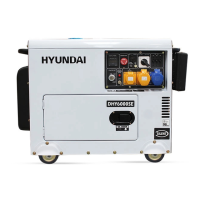
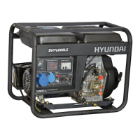
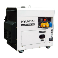
Why won't my Hyundai DHY6000SE diesel engine start?
- MMrs. Cassandra CaseyJul 26, 2025
If your Hyundai Portable Generator's diesel engine won't start, several factors could be at play. First, ensure the governor lever is in the START position. Check that the emergency STOP button isn't activated (depressed) and reset it if it is. Insufficient fuel could also be the culprit, so refill the fuel tank. Additionally, verify the engine oil level, ensuring it reaches the upper lever. Other potential issues include a faulty fuel injection pump (test it after removing), carbon build-up on the injector (clean it), a slow-turning start motor (check battery performance and connections), or a flat battery (charge or replace it).