Do you have a question about the Hyundai Robex 380LC-9 and is the answer not in the manual?
Overview of the service manual's organization and purpose.
Guidance on interpreting page numbering, revisions, and symbols.
Reference for converting measurements such as millimeters to inches.
Essential safety precautions for operating and servicing the excavator.
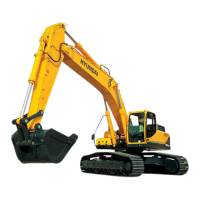
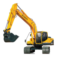
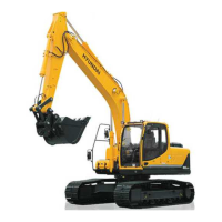
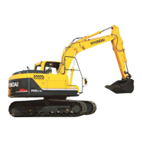
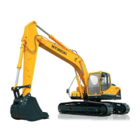
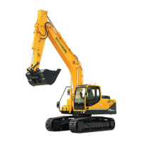
Detailed specifications for the excavator's components and performance.
Details on the structure and function of the pump device.
Details on the structure and function of the main control valve.
Details on the structure and function of the swing device.
Details on the structure and function of the travel device.
Details on the structure and function of the Rcv lever.
Details on the structure and function of the Rcv pedal.
Explanation of the hydraulic circuit diagrams and operation.
Identification of electrical component locations on the machine.
Diagrams and explanations of the machine's electrical circuits.
Introduction and overview of the mechatronics system.
Details on the machine's different operating mode selection systems.
Explanation of the automatic deceleration system's function.
Description of the power boost system's operation.
Details on the travel speed control system.
Explanation of the automatic warming up system.
Details on the engine overheat prevention system.
Explanation of the variable power control system.
Details on the attachment flow control system.
Explanation of the anti-restart system.
Information on the self-diagnostic system, error codes, and fault codes.
Details on the engine control module (ECM) and assembly.
Information on the Eppr valve's types and functions.
Details on the machine's monitoring system and cluster.
Specifications, operation, and circuit of the fuel warmer system.
Preliminary steps and procedures before starting troubleshooting.
Important precautions for disassembly and assembly procedures.
Specifications for tightening torque of major components.
Procedures for removal, installation, and assembly of the pump device.
Procedures for removal, installation, and assembly of the main control valve.
Procedures for removal, installation, and assembly of the swing device.
Procedures for removal, installation, and assembly of the travel device.
Procedures for removal, installation, and assembly of the Rcv lever.
Procedures for removal, installation, and assembly of the turning joint.
Procedures for removal, installation, and assembly of cylinders.
Procedures for removal, installation, and assembly of undercarriage components.
Procedures for removal, installation, and assembly of work equipment.
Introduction to component mounting torque specifications.
Mounting torque specifications for engine system components.
Mounting torque specifications for electric system components.
Mounting torque specifications for hydraulic system components.
Mounting torque specifications for undercarriage components.
Mounting torque specifications for structural components.
Mounting torque specifications for work equipment components.
| Operating Weight | 38, 000 kg |
|---|---|
| Engine Model | Cummins QSL9 |
| Travel Speed (High) | 5.5 km/h |
| Travel Speed (Low) | 3.2 km/h |
| Maximum Digging Depth | 7, 840 mm |
| Swing Speed | 9.7 rpm |
| Bucket Capacity | 1.6 - 2.2 m³ |