Do you have a question about the Hyundai Robex 320LC-9 and is the answer not in the manual?
Explains the manual's purpose and structure.
Guides users on how to use the manual effectively.
Provides conversion tables for units of measurement.
Safety precautions for operation and maintenance.
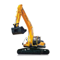
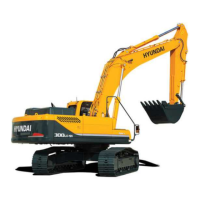
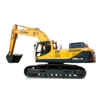
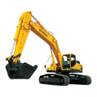
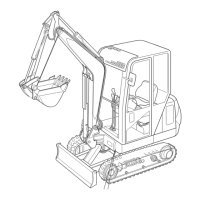
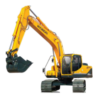
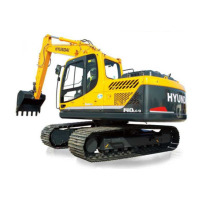
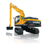
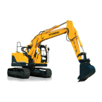
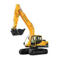
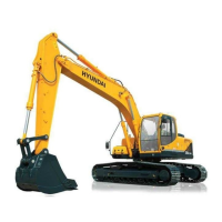
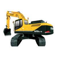
Details technical specifications and dimensions of the excavator.
Illustrates the major components of the excavator with labels.
Details technical specifications for various excavator models.
Details lifting capacities based on load point height and radius.
Describes the structure and function of the pump device.
Details the structure and hydraulic circuits of the control valve.
Explains the structure and function of the swing device.
Covers the construction, specification, and operation of the travel device.
Presents the overall hydraulic circuit diagram.
Details the suction, delivery, and drain circuits of the main hydraulic system.
Explains the pilot circuit, safety valve, and control systems.
Describes the operation of individual excavator functions.
Shows the location of electrical components on the machine.
Lists various electrical circuits like power, starting, and charging.
Provides specifications for electrical components.
Explains different operating mode selection systems.
Details the automatic deceleration system.
Details the self-diagnostic system and error codes.
Covers introduction and diagnosing procedures for troubleshooting.
Details troubleshooting for hydraulic and mechanical systems.
Troubleshooting for electrical system issues.
Covers purpose, terminology, and performance tests.
Maintenance standards for major components.
Safety precautions for removal, installation, and assembly.
Details tightening torque for components.
Disassembly and assembly of the pump device.
Disassembly and assembly of the main control valve.
General guide for component mounting torque.
Mounting torque specifications for the engine system.
Mounting torque specifications for the electric system.
Mounting torque specifications for the hydraulic system.
| Brand | Hyundai |
|---|---|
| Model | Robex 320LC-9 |
| Category | Excavators |
| Language | English |