Do you have a question about the Hyundai Robex 330LC-9A and is the answer not in the manual?
Covers essential safety precautions and guidelines for operating and servicing the equipment.
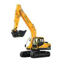
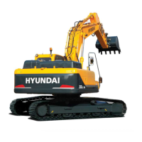
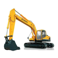
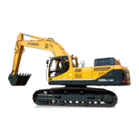
Provides detailed technical specifications for the excavator model.
Details the structure and operational function of the pump device.
Explains the structure, function, and hydraulic circuits of the main control valve.
Describes the structure and function of the Type 1 swing device.
Details the construction, specifications, and operating principles of the travel device.
Illustrates the overall hydraulic circuit diagram.
Details the components and flow of the main hydraulic circuit.
Explains the components and function of the pilot hydraulic circuit.
Describes the hydraulic operations for individual machine functions.
Identifies the location of electrical system components.
Presents the electrical circuit diagrams for the machine.
Provides an overview of the mechatronics system.
Explains the various operating mode selection systems.
Describes the function and operation of the power boost system.
Covers the self-diagnostic system, error codes, and fault diagnosis.
Provides preliminary steps and diagnosis procedures for troubleshooting.
Covers troubleshooting for hydraulic and mechanical system issues.
Details troubleshooting procedures for electrical system faults.
Addresses troubleshooting for mechatronics system malfunctions.
Outlines procedures and standards for operational performance tests.
Provides maintenance standards for major machine components.
Covers essential precautions for disassembly and assembly operations.
Provides torque specifications for major components.
Details the removal, installation, and assembly of the pump device.
Explains the removal, installation, disassembly, and assembly of the main control valve.
Provides an introductory guide to component mounting torque.
Details mounting torque specifications for the engine system.
Provides mounting torque specifications for the electrical system.
Details mounting torque specifications for the hydraulic system.
| Brand | Hyundai |
|---|---|
| Model | Robex 330LC-9A |
| Category | Excavators |
| Language | English |