Do you have a question about the I-Gard SIGMA 3 and is the answer not in the manual?
Lists the voltage and current sensors, NGRS, NGRX, and NGRXS components used with Sigma 3.
Explains how the Sigma 3 detects ground faults using a zero sequence sensor and trip settings.
Describes how the Sigma 3 monitors NGR health (open/short circuit) using measurement or injection modes.
Details the pulsing technique for ground fault location and its implementation with the Sigma 3.
Explains the trip relay operation modes (shunt trip, failsafe) and contact configurations.
Describes the Form-C auxiliary contact for NGR faults, its terminals and operation.
Details the Form-C auxiliary contact for ground faults, its terminals and operation.
Explains the watchdog function and its terminal status for system normal operation.
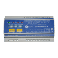
Describes the LED behavior during start-up, reset, and normal operation.
Explains the function of the Green PWR LED indicating power and operational status.
Describes the Red GND FAULT LED status for ground fault detection and qualification.
Details the Red NGR FAULT LED status for NGR fault detection and qualification.
Explains the FUNCTION LED status for ZONE I/L input, self-test, and DIP switch adjustments.
Explains how to set trip relay operating modes (shunt trip, failsafe) using DIP switch 1.
Explains the trip memory setting using DIP switch 2 to store relay states after power loss.
Details setting the ground fault trip time delay using DIP switches 3-7.
Explains setting the ground fault trip current level as a percentage of NGR let-through current.
Describes how to select the system frequency (50Hz or 60Hz) using DIP switch 11.
Details setting the NGR let-through current using DIP switches 12-16.
Provides a summary of DIP switch configurations for various settings.
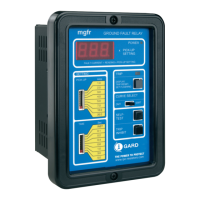
Outlines the display, configuration, and control capabilities of the Sigma3-TDM.
Explains the supported MODBUS functions, registers, and communication models.
Details the location, mounting, and electrical connections for the Sigma 3 relay.
Explains the location, mounting, and connections for the Zero Sequence Current Sensor (ZSCS).
Describes the NGRS-XX sensing resistor, its location, mounting, and connections.
Details the procedure for calibrating the Sigma 3, including pre-calibration and offline calibration.
Guides through the process of online calibration using the Sigma3-TDM touchscreen interface.
Warns about potential damage from field hi-pot/dielectric testing and preparation steps.
Specifies requirements for ground-fault protection and supply de-energization in mine environments.
Outlines the characteristics and monitoring requirements for neutral-grounding devices.