5-5
TROUBLESHOOTING
DC SERIES COMBI BOILERS DC 23-84, DC 29-106, DC 33-124, DC 33-160
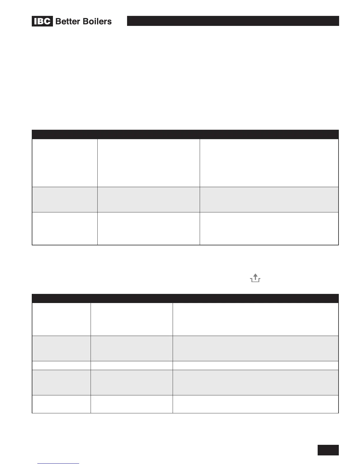
5.3 WARNINGS AND FAULTS
5.3.1 Warning Codes
During operation the controller can detect unusual situations and can take action to avoid damage to the heat
exchanger or other unsafe operations. During these situations the controller will limit the temperature and power
output of the burner, or temporarily disable operation entirely.
These warnings are shown ashing and visible on the main display, and only displayed when an unusual reading is
currently detected.
MAIN DISPLAY DISPLAY FAULT POSSIBLE SOLUTION
E1 Flue gas temperature approaching limit
• Supply water temperature too high
• Ambient temperature too high
• Check positioning of ue gas sensor
• Heat exchanger front panel loose, check bolt torque
• Check heat exchanger for contamination or debris
• Replace ue gas temperature sensor
[pressure] P CH Pressure too low
• Bring the system back up to pressure
• Check pressure sensor
• Replace pressure sensor
POLE Polarity detection fault
• Switch the Line and Neutral wire on the power supply
• Check grounding
• Check for high potential on Neutral wire
• Replace controller
5.3.2 Fault codes
If the fault LED is ashing, the controller has detected a fault. A fault code will be displayed on the main display. Once
the fault has been corrected the burner controller can be restarted. Press the Reset button on the operating panel
to restart the burner controller.
MAIN DISPLAY DISPLAY FAULT POSSIBLE SOLUTION
10, 11, 12, 13, 14 Sensor fault S1
Supply Sensor (upper left side of
the heat exchanger)
• Air in heating system. Bleed the system of any remaining air
• Check the positioning of S1
• Check wiring for break
• Replace S1
20, 21, 22, 23, 24 Sensor fault S2
Return Sensor (lower left side of
the heat exchanger)
• Check the positioning of S2
• Check wiring for break
• Replace S2
0 Sensor fault after self check Replace S1 and/or S2
1 Temperature too high
• Air in system. Bleed the system of any remaining air
• Pump not running, check and/or replace the pump
• Insufcient ow in installation, radiators closed
2 S1 and S2 interchanged
• Check wiring harness
• Replace S1 or S2