1-11
INSTALLATION
HC SERIES BOILERS HC 13-50, HC 23-84, HC 29-106, HC 33-124, HC 20-125, HC 33-160
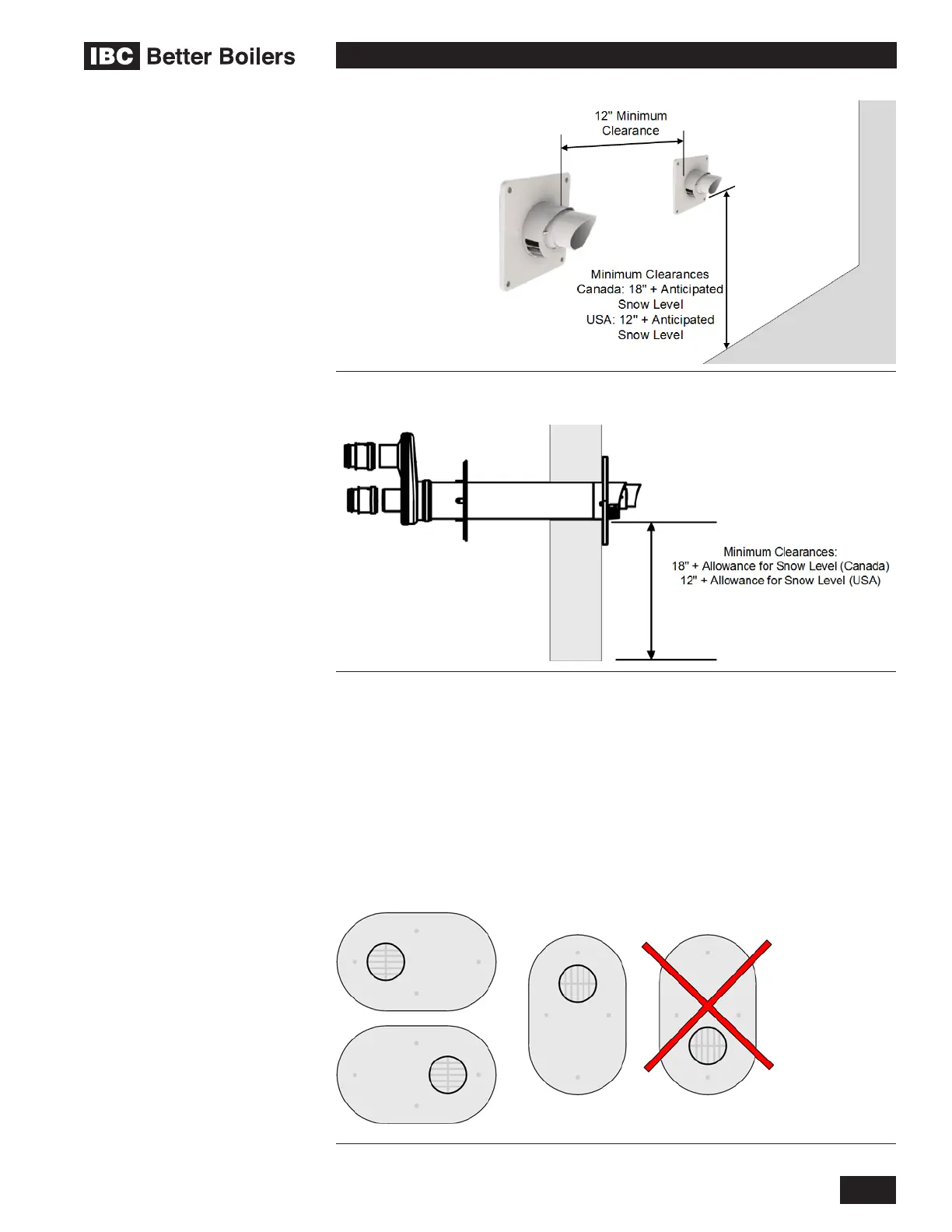
Figure 9a: Horizontal Concentric Termination - Two Kits
Figure 9b: Horizontal Concentric Termination - Single Kit
For side venting of multiple boiler sets, group all intake terminals together with
4" (minimum) lateral spacing, and similarly group the exhaust pipes. Place the
2 groups on the same plane of the building (e.g. north facing wall). Place the 2
groups of pipes at least 3' apart (the closest intake and exhaust pipes shall be
36" - or more – apart. Use same 24" (minimum) vertical separation. Alternately,
as long as the boilers are identical models - intake and exhaust terminals can
maintain a minimum of 12" of separation horizontally from any exhaust or inlet
termination of an adjacent boiler. For alternate group terminations, contact the
IBC Factory for written guidance.
Figure 10: Ipex #196984 2" PVC and #196985 3" PVC – Approved for USA use only
 Loading...


