INSTALLATION AND OPERATION INSTRUCTIONS
1-20
HC SERIES BOILERS HC 13-50, HC 23-84, HC 29-106, HC 20-125, HC 33-160
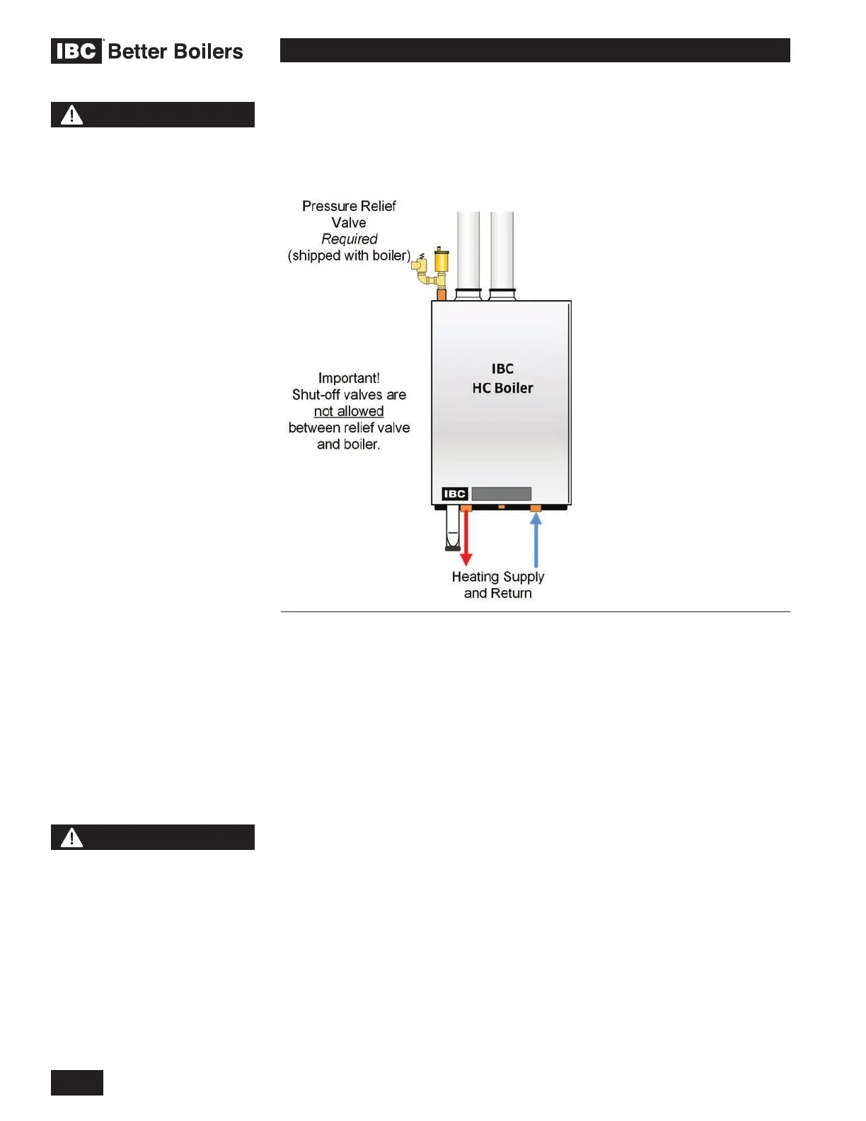
The HC series modulating boilers are designed for use within a closed loop,
forced circulation, low pressure system. A 30 PSI pressure relief valve (3/4" NPT)
is supplied for eld installation at the boilers top connection point. A Relief Valve
and Air Vent Piping Kit is also included with each HC series boiler to aid in the
proper installation of the relief valve and air vent.
System piping is connected to the boiler using the 1" NPT Male threaded ttings
located on the bottom of the boilers. Unions and gate or ball valves at the boilers
supply and return water connections are recommended to simplify servicing. Un-
insulated hot water pipes must be installed with a minimum 1/4" clearance from
combustible materials.
Fluid ll is most often accomplished by using a boiler regulator & ll valve set
at 12 psig or more, with appropriate backow prevention device as required
by local code. This is acceptable in areas where municipal water or well water
has been treated and ltered to remove excessive minerals and sediment, and
water chemistry is known to be suitable for closed loop hydronic systems. In
areas where water quality is in question, or when chemical treatment or glycol is
required, other options should be considered. Follow applicable Codes and good
piping practice.
There are a number of boiler feed and pressurization devices on the market
today that may be a better choice than a raw water ll from the mains. When
regular maintenance requires relief valve blow-off, the discharge may be directed
back into the pressurization unit for recycling of boiler uid and chemicals
back into the system. In buildings that may be unoccupied for long periods of
time, pressurization units are useful to prevent ood damage should leakage
occur from any component in the system. An additional benet is that backow
prevention devices are not required when using these devices.
CAUTION
Installers should inquire of
local water purveyors as to the
suitability of their supply for use
in hydronic heating systems. If
water quality is questionable,
a local water treatment expert
must be consulted for testing,
assessment and, if required,
treatment.
Alternatively, water or hydronic
uid of known quality can be
brought to the site.
WARNING
During operation, the relief
valve may discharge large
amounts of steam and/or hot
water. Therefore, to reduce the
potential for bodily injury and
property damage, a discharge
line MUST be installed that it:
1. is connected from the
valve outlet with no
intervening valve and
directed downward to a
safe point of discharge.
2. allows complete drainage
of both the valve and the
discharge line.
3.
is independently supported
and securely anchored so
as to avoid applied stress
on the valve.
4. is as short and straight as
possible
5. terminates freely to
atmosphere where any
discharge will be clearly
visible and is at no risk of
freezing.
6. terminates with a plain end
which is not threaded.
7. is constructed of a material
suitable for exposure to
temperatures of 375°F or
greater.
8. is, over its entire length,
of a pipe size equal to or
greater than that of the
valve outlet.
DO NOT CAP, PLUG OR
OTHERWISE OBSTRUCT THE
DISCHARGE PIPE OUTLET!
Figure 23: Relief Piping
 Loading...


