1-3
INSTALLATION
HC SERIES BOILERS HC 13-50, HC 23-84, HC 29-106, HC 20-125, HC 33-160
SURFACE
DISTANCE FROM
COMBUSTIBLE
SURFACES
RECOMMENDED DISTANCE
FOR INSTALLATION AND
SERVICE
Front 2" 24"
Rear 0" 0"
Left Side 1.5"
6" (labels may be difcult to read with
reduced clearance)
Right Side 4"
6" (labels may be difcult to read with
reduced clearance)
Top 2" 24"
Bottom 8" 24"
Table 2: Clearance from boiler cabinet
A minimum distance below the boiler of 10" is required to provide
clearance for the supplied condensation trap assembly. More clearance will
typically be required to accommodate associated water and gas piping.
EXHAUST VENTING AND AIR INTAKE
It is important to carefully plan the installation to ensure the appropriate
vent materials, travel and termination decisions are incorporated. Specic
attention is warranted to manage the impact of the steam plume normally
experienced at the exhaust terminal of a condensing boiler. Generally,
intake and exhaust pipes should terminate at a rooftop or sterile wall
location, to maximize customer satisfaction. Keep exhaust plumes
well away from all building air intakes including those of neighbouring
properties.
WARNING
Exposed water piping and
associated components
(relief valves, circulators, etc.)
should not be in contact with
combustible materials. Check
local codes for required
clearances and/or provide
adequate insulation.
1.4
DANGER
Do not common vent the HC
modulating series boilers
with any other existing or new
appliance.
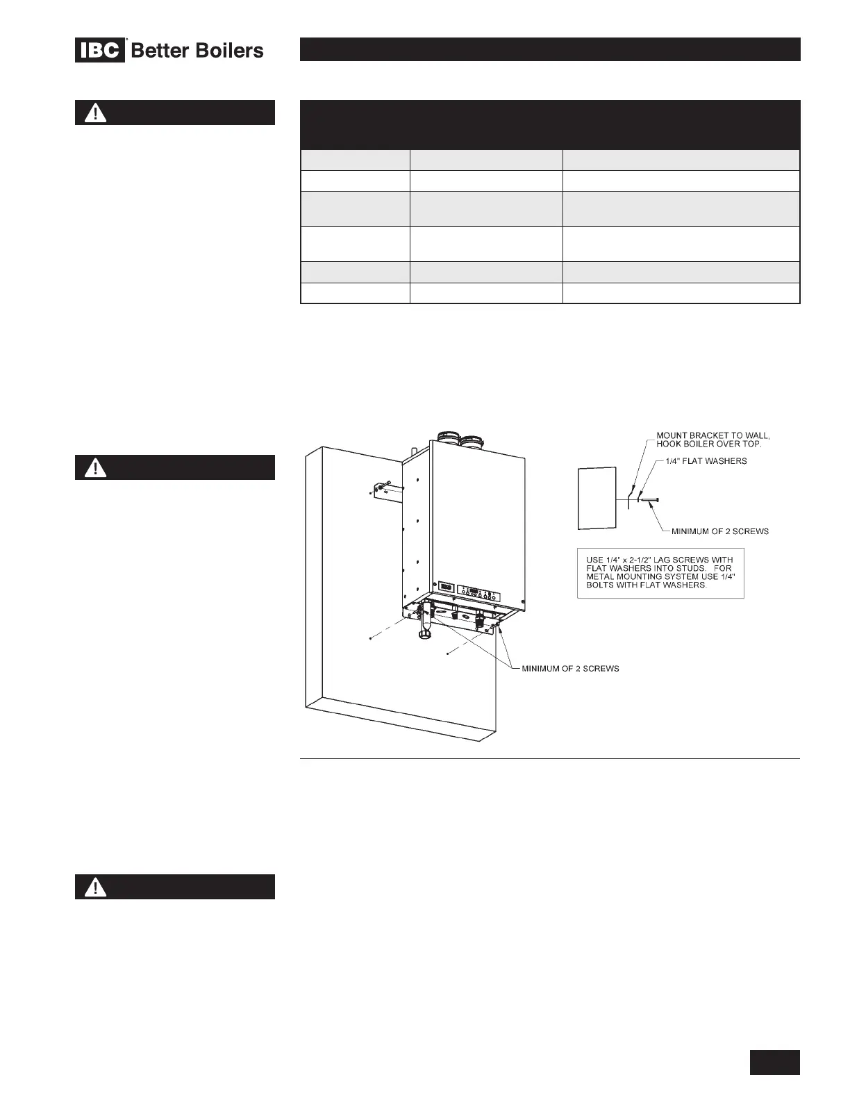
WARNING
DO NOT MOUNT THIS
BOILER TO HOLLOW
WALL STRUCTURES - The
combined weight of the
boiler, its water contents
and associated piping
components can exceed 150
pounds. Fasteners must be
rated for this strain, and must
be rmly anchored into solid
material that will support this
weight.
Installers are to take all
necessary precautions
to avoid injury during the
installation of this boiler.
Figure 2: Wall mounting of boiler
 Loading...


